


26
256-KBPS LINE DRIVER (V.35, RS-530, OR X.21)
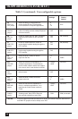
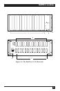
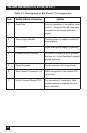
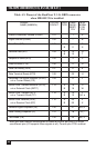
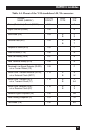
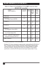
Table 4-1. Descriptions of RackNest 2/14 components.
Item Control, Indicator, or Connector Function
1 Card Slots Slots for installation of compatible cards
(slot no. 1 located at the left-hand side).
Unused slots are closed with blank
panels.
2 Power-Supply Module Provides power to modules installed in
the enclosure.
3 ON Indicator Lights when power supply is operating.
4 Chassis-Ground Terminal Connector for attaching other grounds,
devices, etc., to the RackNest’s chassis
ground (optional).
5 Power Connector Power connector with integral fuse.
6 Main Channel Connectors (J1) DB25 connectors for the module DTE
connection.
7 4-Wire Terminal Blocks (TB1) For connection of 4-wire lines. Each
modem card has a separate terminal-
block connector.