


37
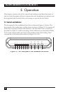
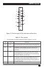
Figure 5-2. The front panel of the rackmount card line driver.
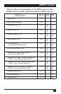
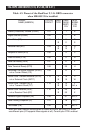
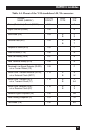
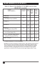
Table 5-1. The controls.
The Item labels in this table correspond to those in Figures 5-1 and 5-2.
ITEM CONTROL FUNCTION
A DIG Pressing the local digital loopback button causes the local LDM-MR256 to
loop received data and clock to its transmitter. Data Set Ready goes low.
B ANA Pressing the local analog loopback (V.54 Loop 3) button causes the local
LDM-MR256 to loop its transmitter output back to its receiver. This
loopback may also be activated from the DTE when the “ALB DTE” jumper
is set to EN.
C REM Pressing the remote digital loopback (V.54 Loop 2) switch causes the
remote LDM-MR256 to loop received data and clock to its transmitter.
Data Set Ready goes low. This loopback may be also activated from the
DTE when the “RLB DTE” strap is set to EN.
D PATT Pressing the PATT button causes the LDM-MR256 to send and receive a
511 test pattern. If errors are encountered, the ERR LED becomes
steadily lit or blinks. Receive Data and Clear to Send go low. Note: The
unit’s “CARRIER” jumper should be set to ON; if it is set to CNTRL, the
RTS signal must be high.
E RPF Remote Power Failure resets the ERR/RPF LED.
PATT
REM
ANA
DIG
PWR
RTS
TD
RD
DCD
TEST ERR
RPF
CHAPTER 5: Operation
1
2
3
4
5
7
E
6
A
B
C
D