


ASUS P5S800-VMASUS P5S800-VM
ASUS P5S800-VMASUS P5S800-VM
ASUS P5S800-VM
1-231-23
1-231-23
1-23
4.4.
4.4.
4.
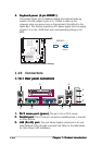
Line In port (light blue).Line In port (light blue).
Line In port (light blue).Line In port (light blue).
Line In port (light blue). This port connects a tape, CD, DVD
player, or other audio sources. In 4-channel and 6-channel
configuration, the function of this port becomes Front Speaker Out.
5.5.
5.5.
5.
Line Out port (lime).Line Out port (lime).
Line Out port (lime).Line Out port (lime).
Line Out port (lime). This port connects a headphone or a
speaker. In 4-channel and 6-channel configuration, the function of this
port becomes Rear Speaker Out.
6.6.
6.6.
6.
Microphone port (pink). Microphone port (pink).
Microphone port (pink). Microphone port (pink).
Microphone port (pink). This port connects a microphone. In a
6-channel configuration, the function of this port becomes Center/
Subwoofer.
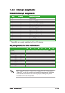
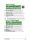
LAN port LED indicationsLAN port LED indications
LAN port LED indicationsLAN port LED indications
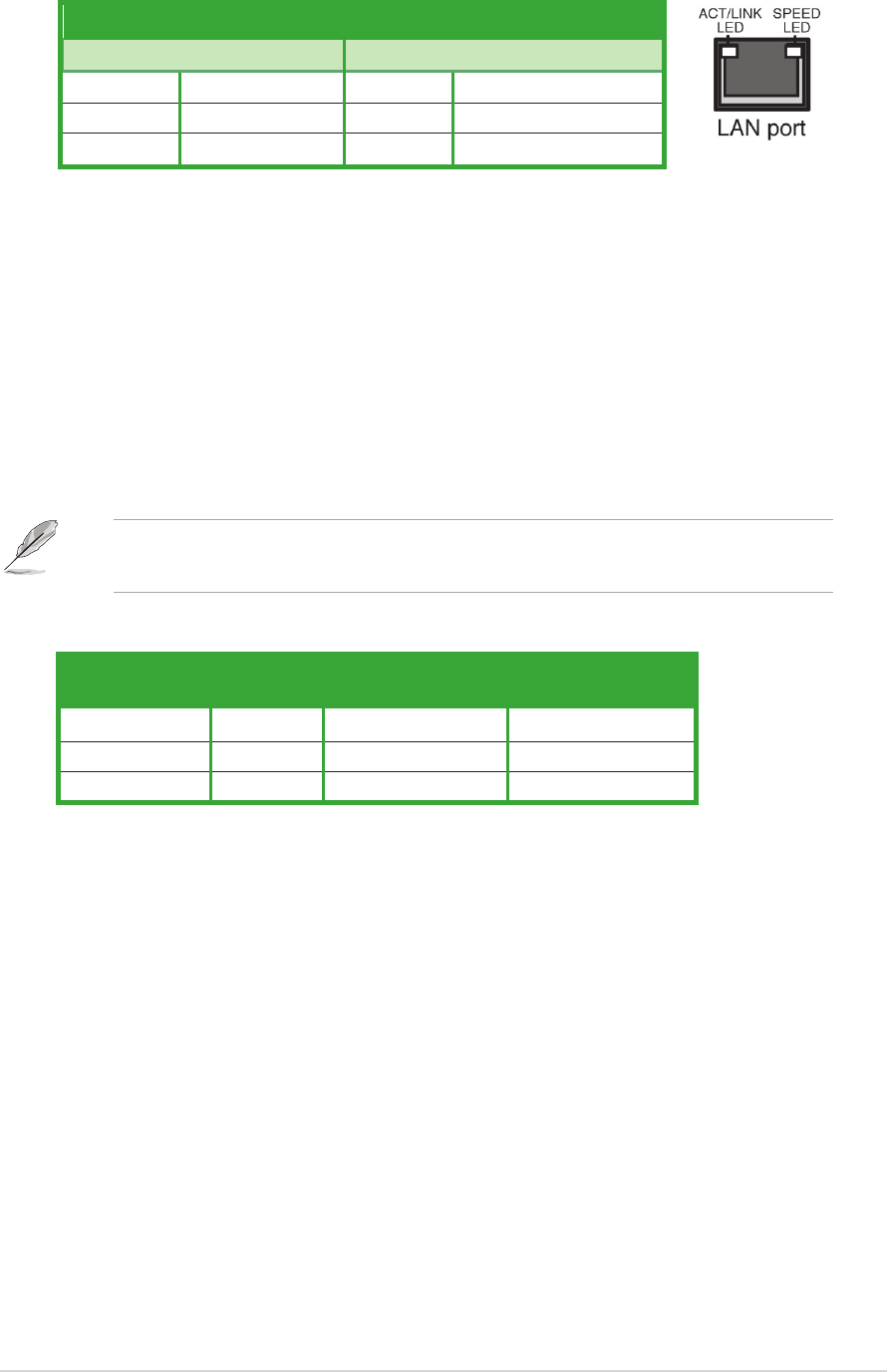
LAN port LED indications
ACT/LINK LED ACT/LINK LED
ACT/LINK LED ACT/LINK LED
ACT/LINK LED
SPEED LED SPEED LED
SPEED LED SPEED LED
SPEED LED
StatusStatus
StatusStatus
Status
DescriptionDescription
DescriptionDescription
Description
StatusStatus
StatusStatus
Status
DescriptionDescription
DescriptionDescription
Description
OFF No link OFF 10 Mbps connection
GREEN Linked ORANGE 100 Mbps connection
BLINKING Data activity
Audio 2, 4, or 6-channel configurationAudio 2, 4, or 6-channel configuration
Audio 2, 4, or 6-channel configurationAudio 2, 4, or 6-channel configuration
Audio 2, 4, or 6-channel configuration
Light Blue Line In Front Speaker Out Front Speaker Out
Lime Line Out Rear Speaker Out Rear Speaker Out
Pink Mic In Mic In Center/Subwoofer
PortPort
PortPort
Port
HeadsetHeadset
HeadsetHeadset
Headset
4-channel4-channel
4-channel4-channel
4-channel
6-channel6-channel
6-channel6-channel
6-channel
2-channel2-channel
2-channel2-channel
2-channel
Refer to the audio configuration table for the function of the audio ports
in 2, 4, or 6-channel configuration.
7.7.
7.7.
7.
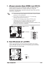
USB 2.0 ports 3 and 4.USB 2.0 ports 3 and 4.
USB 2.0 ports 3 and 4.USB 2.0 ports 3 and 4.
USB 2.0 ports 3 and 4. These two 4-pin Universal Serial Bus
(USB) ports are available for connecting USB 2.0 devices.
8.8.
8.8.
8.
USB 2.0 ports 1 and 2.USB 2.0 ports 1 and 2.
USB 2.0 ports 1 and 2.USB 2.0 ports 1 and 2.
USB 2.0 ports 1 and 2. These two 4-pin Universal Serial Bus
(USB) ports are available for connecting USB 2.0 devices.
9.9.
9.9.
9.
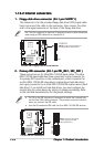
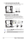
VGA port.VGA port.
VGA port.VGA port.
VGA port. This 15-pin VGA port connects to a VGA monitor.
10.10.
10.10.
10.
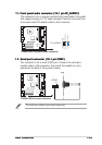
Serial connector. Serial connector.
Serial connector. Serial connector.
Serial connector. This 9-pin COM1 port is for serial devices.
11.11.
11.11.
11.
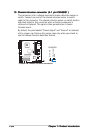
PS/2 keyboard port (purple).PS/2 keyboard port (purple).
PS/2 keyboard port (purple).PS/2 keyboard port (purple).
PS/2 keyboard port (purple). This port is for a PS/2 keyboard.