


ASUS P5S800-VMASUS P5S800-VM
ASUS P5S800-VMASUS P5S800-VM
ASUS P5S800-VM
1-271-27
1-271-27
1-27
7.7.
7.7.
7.
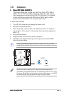
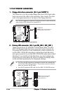
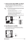
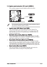
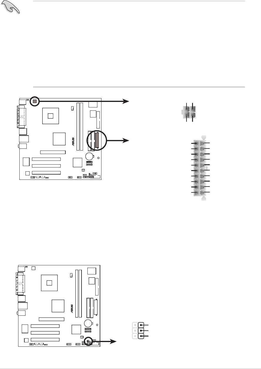
ATX power connectors (20-pin ATXPWR1,ATX power connectors (20-pin ATXPWR1,
ATX power connectors (20-pin ATXPWR1,ATX power connectors (20-pin ATXPWR1,
ATX power connectors (20-pin ATXPWR1,
4-pin ATX12V1)4-pin ATX12V1)
4-pin ATX12V1)4-pin ATX12V1)
4-pin ATX12V1)
These connectors are for an ATX power supply. The plugs from the
power supply are designed to fit these connectors in only one
orientation. Find the proper orientation and push down firmly until the
connectors completely fit.
8.8.
8.8.
8.
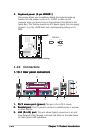
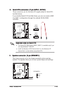
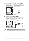
Power LED connector (3-1 pin PLED1)Power LED connector (3-1 pin PLED1)
Power LED connector (3-1 pin PLED1)Power LED connector (3-1 pin PLED1)
Power LED connector (3-1 pin PLED1)
This 3-1 pin connector is for the system power LED. The system
power LED lights up when you turn on the system power, and blinks
when the system is in sleep mode.
•
You can also use a Power Supply Unit (PSU) with a 24-pin ATX power
connector on this motherboard.
•
Do not forget to connect the 4-pin ATX +12 V power plug;
otherwise, the system will not boot up.
• Use a PSU with a minimum power rating of 300 W on this
motherboard. Use of a PSU with a higher power output is
recommended when configuring a system with more
power-consuming devices. The system may become unstable or may
not boot up if the power is inadequate.
P5S800-VM
®
P5S800-VM ATX power connectors
ATXPWR1
ATX12V1
+3.3VDC
-12.0VDC
COM
PS_ON#
COM
COM
COM
-5.0VDC
+5.0VDC
+5.0VDC
PWR_OK
+12.0VDC
+3.3VDC
+3.3VDC
COM
+5.0VDC
COM
+5.0VDC
COM
+5VSB
+12V DC GND
+12V DC GND
P5S800-VM
®
P5S800-VM PLED connector
PLED1
PLED+
1
NC
PLED-