


D9210B
Installation
D9210B Operation and Installation Guide
© 2002 Bosch Security Systems Page 15 32206G
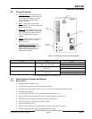
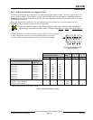
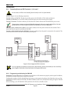
Note:
NOTE:
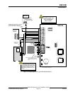
A24VDCpowersupplymaybeusedforthedoor
strike if necessary. (See Figure 5)
Strike and
D9210B
This color codedoesnotmatch
all readers.Makea noteof the
color code of the reader you are
using.
1
PWR +
7
SDIB
6
SDIA
5
COM
8
T+
10
ZN +
9
ZNCOM
2
LCKN/C
3
LCKCOM
4
LCKN/O
13
REX
12
COM
11
RTE
16
DATA 1
17
BUZZER
18
LED
15
DATA 0
14
+5.20V
D0
READER
OPER
MON
D1
READER
1
2
3
4
5
6
ON
D9210B
(red)
12 VDC AUX
Power Supply
UL Listed for Fire
DC OUTPUT
+
-
(black)
(white/yellow)
(green)
SDI
PWR
SDI
A
SDI
B
SDI
COM
Security
Panel
(black)
EMERGENCY
EGRESS
DOOR
DOORCONTACT
(NORMAL E.O.L.
IN CIRCUIT)
1K
E.O.L.
RTE/REX
(NORMAL
OPEN)
(white)
(green)
(red)
(brown)
12VDC
BUZZER
12 VDC READER
(+)
(-)
(yellow)
TAMPER SWITCH
(NORMALOPEN)
(black)
12 VDC
DOOR
STRIKE
Some jurisdictions will not allowthe
use of Emergency Egress as your sole
means of escape. Ifthisfeature is used,
it still may be necessary to provide listed
panic hardware. Consultyour local
authority having jurisdiction (AHJ) prior to
nstallation.
DO NOT power the
D9210B Module
with 24 VDC.
CAUTION
CAUTION
EMERGENCY EGRESS Switch should be
Normally Open (NO) for CoilLocks and
Normally Closed (NC) for Maglocks
Figure 2: Wiring Diagram for Typical D9210B Installation