


D9210B
Contents
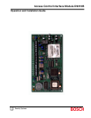
D9210B Operation and Installation Guide
32206G Page 4 © 2002 Bosch Security Systems
5.1 LED Troubleshooting .......................................................................................................................................................25
Appendix A: D9210B Terminal Quick Reference and Electrical Specifications..............................................................27
Figures
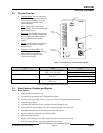
Figure 1: D9210B Access Control Interface Module................................................................................................................ 9
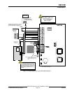
Figure 2: Wiring Diagram for Typical D9210B Installation.....................................................................................................15
Figure 3: Relay Installation .............................................................................................................................................................17
Figure 4: D9210B DIP Switch (Factory Settings)....................................................................................................................19
Figure 5: Power Supply and SDI Connections .........................................................................................................................20
Figure 6: D9210B Door Release Application Connections...................................................................................................23
Tables
Table 1: D9210B Operation and Installation Guide Document Organization ..................................................................... 5
Table 2: Other Literature Referenced............................................................................................................................................5
Table 3: D9210B Diagnostic and Status LEDs..........................................................................................................................9
Table 4: Typical Wire Planning Chart for the D9210B ...........................................................................................................14
Table 5: Point Tolerance Voltages ...............................................................................................................................................16
Table 6: Door Lock Strikes.............................................................................................................................................................17
Table 7: UL Listed Compatible Readers for the D9210B ......................................................................................................18
Table 8: D9210B Dipswitch Settings .........................................................................................................................................19
Table 9: LED Troubleshooting Guide..........................................................................................................................................25
Table 10: Terminal Quick Reference Guide and Electrical Specifications.........................................................................27