


D9210B
Appendix A: D9210B Terminal Quick Reference
and Electrical Specifications
D9210B Operation and Installation Guide
© 2002 Bosch Security Systems Page 27 32206G
Appendix A: D9210B Terminal Quick Reference
and Electrical Specifications
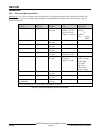
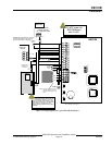
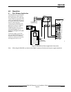
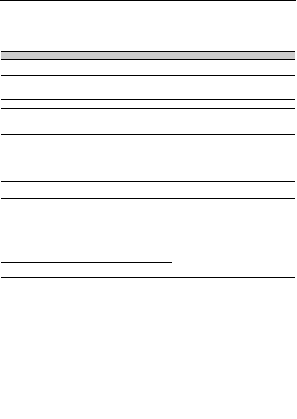
Terminal Description Electrical Specifications
1 PWR + 12 VDC power input
• 8.5 - 13.8V [depending on reader draw: 110
mA (board) + 150 mA (reader max) = 260 mA]
2 LCK N/C Continuity with LCK COM when relay is off.
• 12/24 V @ 2.0 A max (30 VDC max)
3 LCK COM
Input to feed LCK N/C (T2) and Lock N/O
(T3)
4 LCK N/O Continuity with LCK COM when relay is on.
• 12/24 V @ 2.0 A max (30 VDC max)
5 COMMON Common Input (power for lock and device)
6 SDI A Data from the panel to the D9210B
• high impedance bi-directional differential bus
7 SDI B Data back to the panel from the D9210B RS-485 @ 9600 baud
8 T + Positive input for Tamper, normally open
• open collector input 1 kΩ pull up
• V in < 1.8 V on > 3.2 V off
9 ZNCOM Common input for on-board point
• 1K Ω termination resistor between T9 and
T10 required
1
0
ZN + Positive Input for on-board point
1
1
RTE Input from Request to Enter (RTE) momentary
short device
• open collector input 1kΩ pull up
• V in < 1.8 V on > 3.2 V off
1
2
COM Common input for REX/RTE devices
1
3
REX Input from Request to Exit (REX) momentary
short device
• open collector input 1 kΩ pull up
• V in < 1.8 V on > 3.2 V off
1
4
+5.2 V Power out to 5.2 VDC card reader.
• V out 5 V ± .25 V for 20 - 140 mA load
• 150 mA maximum continuous
1
5
DATA 0 Data 0 input from card reader (activates D0
LED)
• high impedance differential inputs with 10 kΩ
pull up to +5.2 V
1
6
DATA 1
Data 1 input from card reader (activates D1
LED)
1
7
BUZZER Buzzer common upon strike activation.
• sink up to 35 mA from 5 - 14 VDC source
• output impedance is 100 Ω
1
8
LED LED common upon card read response and
strike activation.
• sink up to 35 mA from 5 - 14 VDC source
• output impedance is 180 Ω
Table 10: Terminal Quick Reference Guide and Electrical Specifications