


COMPUTER IN
MONITOR OUT
CONTROL PORT
AUDIO IN
SERIAL
AUDIO OUT
(MONO)
VIDEOR–AUDIO–L
S-VIDEO
10
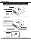
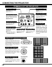
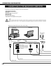
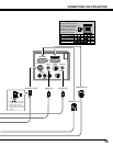
CONNECTING THE PROJECTOR
TERMINALS OF THE PROJECTOR
Connect the computer output
to this terminal.
(Refer to P12 ~15.)
When controlling the computer
with the Remote Control of this
projector, connect the mouse
port to this connector.
(Refer to P12 ~15.)
Connect the monitor to this
terminal.
(Refer to P12 ~15.)
This connector is used to
connect a computer to control
this projector with the PC.
(Refer to P12 ~13.)
Connect the audio amplifier to
this jack.
(Refer to P12 ~15.)
Connect the S-VIDEO
output from the video
equipment to this jack.
(Refer to P11.)
Connect the audio output from
the computer to this jack.
(Refer to P12 ~15.)
Connect the audio outputs
from the video equipment
to these jacks.
(Refer to P11.)
● When the audio output is
monaural, connect it to
the AUDIO LEFT jack.
Connect the video
output from the video
equipment to this jack.
(Refer to P11.)
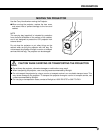
This projector uses a micro
processor to control the unit.
Occasionally, the micro
processor may malfunction and
need to be reset. This can be
done by pressing the RESET
button with a pen, which will
shut down the unit. Turn the
projector off and restart the unit.
Do not use the RESET function
excessively.
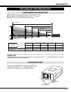
COMPUTER INPUT TERMINAL
MONITOR OUTPUT TERMINAL
COMPUTER AUDIO INPUT JACK
AUDIO INPUT JACKS
VIDEO INPUT JACK
SERIAL PORT CONNECTOR
AUDIO OUTPUT JACK
S-VIDEO INPUT JACK
RESET BUTTON
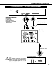
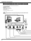
COMPUTER INPUT / MONITOR OUTPUT TERMINAL
Terminal : HDB15-PIN
Connect the display output terminal of the
computer to this COMPUTER INPUT with the
VGA Cable (supplied), and connect the monitor
to this MONITOR OUTPUT with the monitor
cable (not supplied). When connecting the
Macintosh computer, the MAC Adapter is
required (not supplied).
Terminal : MULTI-POLE 12-PIN
When controlling the computer with the
projector's Wireless Remote Control Unit,
connect control port (PS/2, Serial or ADB port)
on your computer to this connector. (Control
Cable for PS/2 Port is supplied.)
5
1
2
34
10
9 678
15
14
13
11
12
1
2
3
4
5
6
7
8
9
10
11
12
Red Input
Ground (Horiz.sync.)
Green Input
Sense 2
Blue Input
Ground (Red)
Ground (Green)
Ground (Blue)
1
5
2
4
3
6
7
8
Non Connect
Horiz. sync.
Ground (Vert.sync.)
Sense 1
Sense 0
Vert. sync.
Reserved
9
13
10
12
11
14
15
-----
CLK
DATA
-----
-----
-----
-----
-----
GND
-----
-----
-----
T X D
-----
-----
-----
R X D
-----
READY
-----
GND
-----
-----
-----
-----
ADB
-----
-----
-----
-----
-----
-----
GND
-----
-----
-----
PS/2 Serial
ADB
1
2
3
4
5
6
7
8
9
10
11
12
Pin Configuration
Pin Configuration
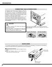
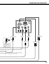
CONTROL PORT CONNECTOR
Terminal : DIN 8-PIN
This connector is used to connect a computer
to control the projector with the PC. For this
connection, the Serial Cable is required (This
cable is not supplied).
1
2
3
4
5
8 7 6
Pin Configuration
SERIAL PORT CONNECTOR
R x D
ADB
GND
MUX232
1
2
4
3
MUXTTL
T x D
–––––
–––––
5
6
8
7
CONTROL PORT CONNECTOR