


Appendix
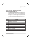
Printer Interface Technical Information
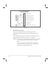
RS-232/RS-422/RS-485 Serial Data Port
The connections for these standard interfaces are made through the DB25S
connector on the rear panel. For all RS-232 input and output signals, the
printer follows both the Electronics Industries Association’s (EIA) RS-232
specifications and the Consultative Committee for International Telegraph
and Telephone (CCITT) V.24 standard signal level specifications.
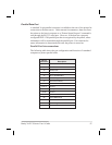
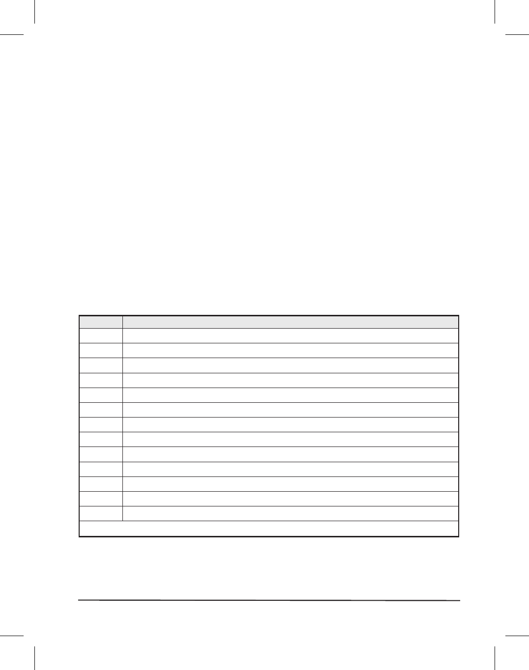
The following table shows the pin configuration and function of the rear
panel serial data connector on the printer.
Pin No. Description
1 FG (frame ground) for cable shield
2 TXD (RS-232 transmit data) output from printer
3 RXD (RS-232 receive data) input to printer
4 RTS (RS-232 request to send) output from printer
6 DSR (data set ready) input to printer
7 SG (signal ground) for RS-232
9 +5 VDC source output (1 Amp maximum)
11 SGR (signal ground reference) for RS-422/RS-485
13 Data input B(-); RS-422/RS-485
14 Data output B(-); RS-422/RS-485
16 Data input A(+); RS-422/RS-485
19 Data output A(+); RS-422/RS-485
20 DTR (RS-232 data terminal ready) output from printer
NOTE: Pins 5, 8, 10, 12, 15, 17-18, 21-25 are not used and are unterminated.
Brady X-PLUS Series User’s Guide 93