


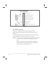
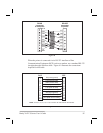
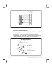

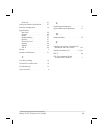

When the printer is connected via its RS-232 interface to Data
Communication Equipment (DCE) such as a modem, use a standard RS-232
(straight-through) interface cable. Figure 41 illustrates the connections
required for this cable.
Brady X-PLUS Series User’s Guide 95
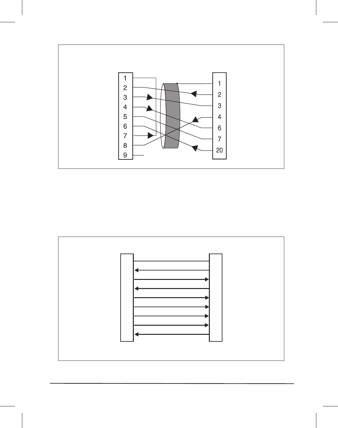
DB-25P
connector
to printer
DB-9S
connector
to computer
FG
TXD
RXD
RTS
DSR
SG
DTR
DCD
RXD
TXD
DTR
SG
DSR
RTS
CTS
RI
Figure 40
1
2
3
4
5
6
7
8
20
1
2
3
4
5
6
7
8
20
FG (frame ground)
DCE DTE
TXD (transmit data)
RXD (receive data)
RTS (request to send)
CTS (clear to send)
DSR (data set ready)
SG (signal ground)
CD (carrier detect)
DTR (data terminal ready)
NOTE: Pins 5, 8, 10, 12, 15, 17-18, 21-25 are not used and are unterminated.
Figure 41