TM
SLE100 Installation Manual
29 590-00532, rev A
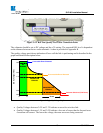
• Quality Voltages between 0.5V and 1.0V indicate excessive errors in the wireless link that can
not be corrected by the FEC. To indicate this change in error performance, the quality voltage
will drop from 1.5V to 1.0V in a single step.
• Quality Voltages below 0.5V indicate an unlocked deframer condition. This will be recognized
as a link-down condition.
The following procedure can be used to check the RSL and quality voltages:
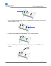
1. To read the RSL value (between 0 and 3.3V), insert GND (ground) and RSL banana plugs into
the voltmeter. Note the RSL voltage. The voltage may be fluctuating; in this case, note the
maximum value seen.
2. To read the Link Quality value of the radio, insert GND (ground) and QUAL banana plugs
into the voltmeter. Note the Link Quality voltage. After an Auto-Calibration has been performed from
the ‘Maintenance’ page of the web interface the quality voltage should read 3.3V if the link is aligned
on the main antenna beam and there are no obstructions (i.e., trees, buildings, etc…) in the path, the
link distance is within the operating parameters of the radio, and it is not raining heavily.
The SLE100 has been designed to require only minimal user configuration. To perform the
configuration of the Network Management System follow the instructions in the Network
Management manual.
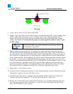
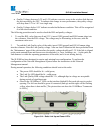
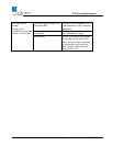
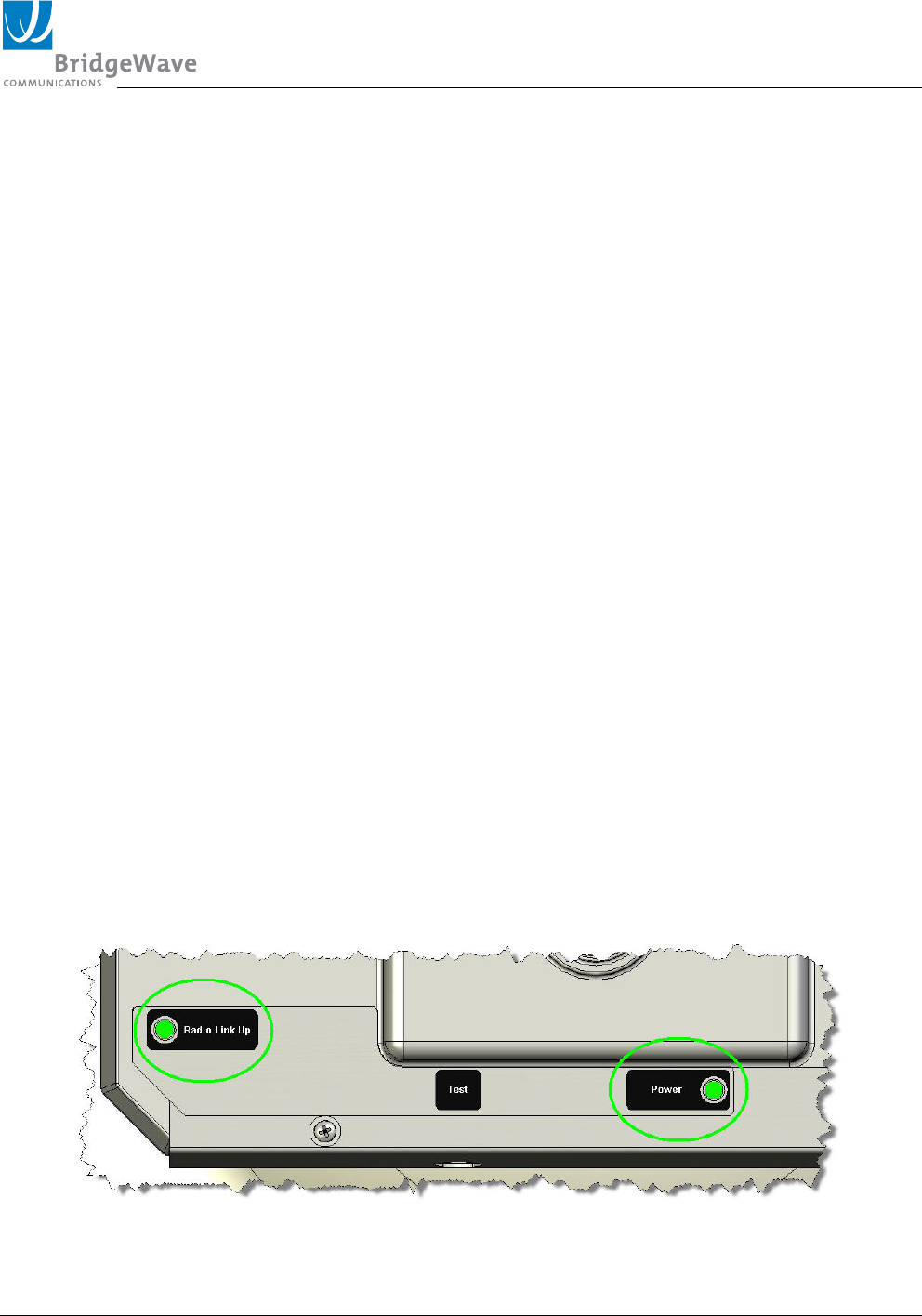
During normal operation, the following conditions should exist at the radio:
• The power LED should be lit—solid green;
• The Link Up LED should be lit—solid green;
• The Link Quality BER voltage should be 3.3v, although dips in voltage are acceptable
during periods of significant rain.
• Observe the 10/100Base-T LEDs on the interface labeled PoE at each side next to socket
opening. The left one should be green if connected (link up) and the right will be flashing
yellow when there is data traffic. [The picture does not show the 10/100Base-T connector
or LEDs]
Figure 3-14: Radio Link Up and Power LED’s


