


Brocade 6910 Ethernet Access Switch Hardware Installation Guide 5
53-1002580-01
Description of Hardware
1
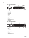
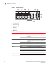
10/100/1000BASE-T Ports
The switches contain 12 1000BASE-T RJ-45 ports that operate at 10 Mbps or 100 Mbps, half or full
duplex, or at 1000 Mbps, full duplex. Because all of the RJ-45 ports support automatic MDI/MDI-X
operation, you can use straight-through cables for all network connections to PCs or servers, or to
other switches or hubs. (See “1000BASE-T Pin Assignments” on page 29.)
Each of these ports support auto-negotiation, so the optimum transmission mode (half or full
duplex), and data rate (10, 100 or 1000 Mbps) can be selected automatically. If a device
connected to one of these ports does not support auto-negotiation, the communication mode of
that port can be configured manually. Each port also supports auto-negotiation of flow control, so
the switch can automatically prevent port buffers from becoming saturated.
10/100/1000BASE-T Management Port (The Craft Interface)
The 10/100/1000BASE-T port provides a dedicated management interface that is segregated
from the data traffic crossing the other ports. This port supports auto-negotiation, so the optimum
transmission mode (half or full duplex) and data rate (10, 100, or 1000 Mbps) can be selected
automatically, if this feature is also supported by the attached device. However, note that the
interface connection parameters of this port cannot be configured.
Console Port
The console port on the switch’s front panel is an RJ-45 connector that enables a connection to a
terminal for performing switch monitoring and configuration functions. The terminal may be a PC or
workstation running terminal emulation software, or a terminal configured as a Data Terminal
Equipment (DTE) connection. A null-modem wired serial cable is supplied with the switch for
connecting to this interface.
It is recommended that you use the cable provided with the box.
Flow control must be disabled to use the console port and port speed is 9600-N-8-1
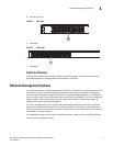
Alarm Interface Port
The DB-15 alarm port on the switch’s front panel can be used to provide alarm, service port, and
BITS clock reference interfaces. The switch supports two sets of alarm relay contacts (major and
minor), and 4 external customer site alarm inputs. It also provides an alarm cutoff button (labeled
ACO). Refer to “Connecting to the Alarm Port” on page 20 for a description of the pin assignments
used to connect to the alarm port.
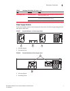
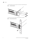
Port and System Status LEDs
This switch includes a display panel for key system and port indications that simplifies installation
and troubleshooting. The LEDs, which are located on the front panel for easy viewing, are shown
below and described in the following tables.