


Brocade 6910 Ethernet Access Switch Hardware Installation Guide 17
53-1002580-01
Connecting to a Power Source
2
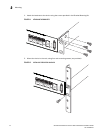
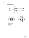
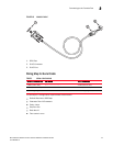
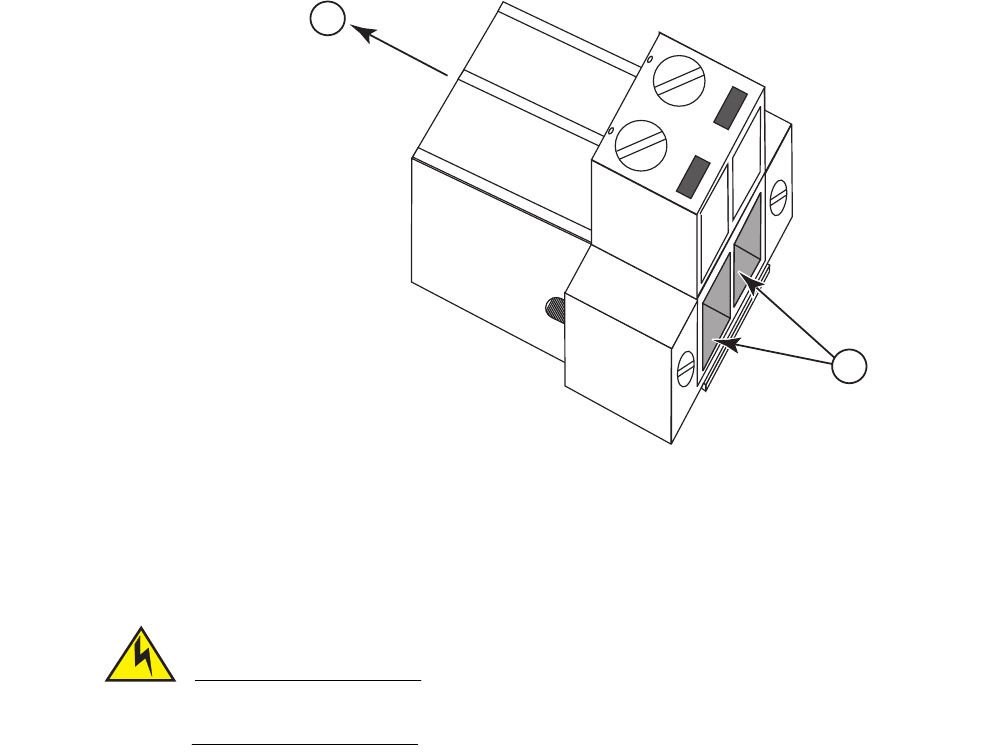
FIGURE 16 DC PLUG CONNECTIONS 2
1. To Switch
2 DC power lines in
7. Insert the wire leads into the openings shown in the figure below. Each lead inserted in the
power plug must match the lead attached to the power source. Use the label above the DC
power connection block to identify the appropriate power input and return or ground lines.
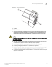
CAUTION
If the power leads are plugged into the wrong holes, the power supply will not work properly and
may damage the switch.
8. Push each wire about half an inch into the opening on the plug, and tighten down the clamp
screw securely. You should not be able to pull on the wire and dislodge it.
9. Insert the power plug in the power receptacle on the left side of the front panel.
10. At the power source, turn on the power for the feed lines or power bus.
11. Check the Power LED indicator as the switch is powered on. If not, recheck the power supply
and power cable connections at the supply source and at power conversion module.
12. To disconnect DC power from the switch, turn off the DC power feed lines before removing the
plugs from the DC sockets.
2
1