


Brocade 6910 Ethernet Access Switch Hardware Installation Guide 23
53-1002580-01
Chapter
3Making Network Connections
In this chapter
•Connecting Network Devices . . . . . . . . . . . . . . . . . . . . . . . . . . . . . . . . . . . . . 23
•Twisted-Pair Devices . . . . . . . . . . . . . . . . . . . . . . . . . . . . . . . . . . . . . . . . . . . . 23
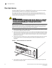
•Fiber Optic Devices . . . . . . . . . . . . . . . . . . . . . . . . . . . . . . . . . . . . . . . . . . . . . 24
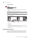
Connecting Network Devices
These switches are designed to connect broadband access network devices to aggregation
network devices in the service provider CO. It can connect to twisted-pair devices through its RJ-45
ports, or to fiber-optic devices through SFP transceivers.
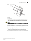
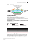
Twisted-Pair Devices
Each device requires an unshielded twisted-pair (UTP) cable with RJ-45 connectors at both ends.
Use Category 5, 5e or 6 cable for 1000BASE-T connections.
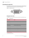
Cabling Guidelines
The RJ-45 ports on the switch support automatic MDI/MDI-X pinout configuration, so you can use
standard straight-through twisted-pair cables to connect to any other network device (PCs, servers,
switches, routers, or hubs). See “Twisted-Pair Cable and Pin Assignments” on page 27 for further
information on cabling.
CAUTION
Do not plug a phone jack connector into an RJ-45 port. This will damage the switch. Use only
twisted-pair cables with RJ-45 connectors that conform to FCC standards.
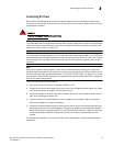
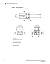
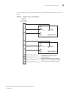
Connecting to PCs, Servers, Hubs and Switches
1. Attach one end of a twisted-pair cable segment to the device’s RJ-45 connector.
2. Attach the other end to an available port on the switch.
3. Make sure each twisted pair cable does not exceed 100 meters (328 ft) in length.
4. As each connection is made, the relevant Port LED (on the switch) corresponding to each port
will light green or amber to indicate that the connection is valid.