


20 Brocade 6910 Ethernet Access Switch Hardware Installation Guide
53-1002580-01
Connecting to the Alarm Port
2
Connecting to the Alarm Port
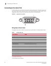
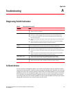
The DB-15 alarm port on the switch’s front panel is used to provide alarm. The switch supports two
sets of alarm relay contacts (major and minor), and 4 external customer site alarm inputs. The pin
assignments used to connect to the alarm port are provided in the following table.
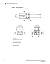
FIGURE 19 ALARM PORT (D-15) PIN OUT
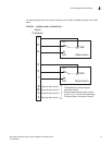
Wiring Map for Alarm Cable
The signals include relay contacts for major and minor system alarms, and external alarm inputs.
* P indicates positive input.
† RTN indicates return to Ground.
TABLE 4 SYSTEM STATUS LEDs
Switch’s Alarm Port Funtion
1 (MJR_ALARM_CNTR) Common contact for major alarm relay.
2 (MNR_ALARM_CNTR) Common contact for minor alarm relay.
3 (ALARM_IN3_EXT_P*) External alarm input 3 (external relay dry contact closure to pin 13).
4 (ALARM_IN4_EXT_P) External alarm input 4 (external relay dry contact closure to pin 8).
5 (No Contact)
6 (MJR_ALARM_NO) Normally open during major alarm state.
7 (MNR_ALARM_NO) Normally open during minor alarm state.
8 (ALARM_IN4_EXT_RTN†) External alarm input 4 (external relay dry contact closure from pin 3).
9 (ALARM_IN1_EXT_P) External alarm input 1 (external relay dry contact closure to pin14).
10 (ALARM_IN2_EXT_P) External alarm input 2 (external relay dry contact closure to pin 15).
11 (MJR_ALARM_NC) Normally closed during major alarm state.
12 (MNR_ALARM_NC) Normally closed during minor alarm state.
13 (ALARM_IN3_EXT_RTN) External alarm input 3 (external relay dry contact closure from pin 3).
14 (ALARM_IN1_EXT_RTN) External alarm input 1 (external relay dry contact closure from pin 9).
15 (ALARM_IN2_EXT_RTN) External alarm input 2 (external relay dry contact closure from pin 10).
15
1