


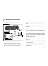

7. Starting up
30
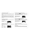
carries the video signal and must be inserted into the "video”
socket, the red one goes into "audio right”, and the white one
into "audio left”.
3. Set one of the channels 1 to 4 at the channel switch.
Note. If the AVS 850 Power Transmitter and the AVS 840
Power Receiver are to work together, they have to be set
both at the same wireless channel.
4. Insert the mains adapter into a 230 V mains socket and the
9V plug into the socket provided. Never use any other mains
adapter than this one.
5. Switch the Power Receiver on with the "On” (I) switch (the
LED at the front lights up).
Place the AVS 840 Power Receiver in a favourable position, e.g.
on top of the television set.,
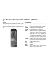
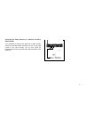
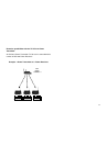
NOTE: To control the cable tuner in the AVS 850 or the video
recorder to which the AVS 850 Power Transmitter is connected,
point the RC 815 cable-tuner remote-control unit, or use the
original remote-control unit of the video recorder, at the infra-red
eye of the AVS 840 on the front side.
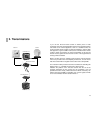
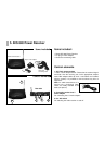
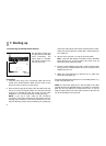
The AVS 840 receives the
AV signal from the AVS 850
Power Transmitter. The
output signal is available
from the AV sockets on the
rear side of the unit.
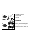
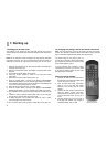
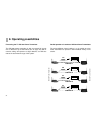
Connecting:
1. Insert the cinch plug of the connecting cable into the AV
socket of the Power Receiver. Make sure the colour on the
plug is the same as the one on the socket.
2. Now connect the plug at the other end of the cable to the unit
that is to receive the signals. Make sure that the enclosed
scart plug is inserted the right way round. Use the cable
labelled "In”. Do not exert force when inserting the plug!
NOTE: If you use a cinch cable for the connection
(accessory), note when connecting the unit that the colour of
the plug has to match the colour of the socket on the unit. If
they are different, please note the following: the yellow plug
7.2 Connecting the AVS 850 Power Receiver