


27
4. Channel and switch settings.
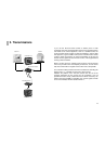
The AVS 840 Power Receiver can be operated in one of two
ways:
1. Permanent reception of a given wireless channel (cable TV or
video).
2. Switching between the pre-set wireless channels at pre-
determined intervals. This function is necessary when, for
instance, the Power Receiver is to be used with a number of
different wireless monitor cameras with the AVS 850 Power
Transmitter.
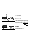
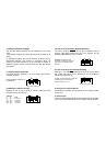
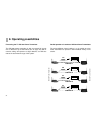
4.1 Channel switch (rear side)
4 channel switches (switches 1 to 4) for setting the wireless-
reception channel.
In this example, Channel 2
is activated.
4.2 Setting the switch-over time
Switches 5 and 6 can be used to set the switch-over time
between the pre-set channels.
4.3 Use as receiver without
channel switching
The same channel must be set on the transmitter and the
receiver. This facility means that up to four systems can be
operated independently of one another.
4.4 Use as receiver with
channel switching
Switches 1 to 4 enable the channels to be set to each of which
the system will switch in turn. Switches 5 and 6 enable the
switch-over time to be set.
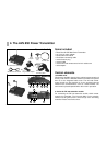
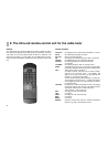
5. Aerial for the control channel
Transmits the 433 MHz control signals of the original remote-
control unit.
6. Infra-red eye
This is the point towards which the unit connected to the remote-
control unit of the AVS 850 Power Transmitter must be pointed.
1
2 3 4 5 6
on
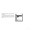
AVS 840 Power Receiver
CH T
Timetable:
5 6 Time
ON ON 8 seconds
ON OFF 4 seconds
OFF ON 2 seconds
OFF OFF 1 seconds
1
2 3 4 5 6
on
AVS 840 Power Receiver
CH T
Example: the AVS 840 Power
Transmitter is sending the signal via
Channel 2 to the AVS 850 Power
Receiver.
Example: the AVS 840 Power Transmitter
is switching at 4-second intervals
between Channels 1 and 2.
1
2 3 4 5 6
on
AVS 840 Power Receiver
CH T
1
2 3 4 5 6
on
AVS 840 Power Receiver
CH T