


25
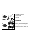
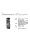
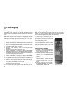
3. Channel switch
The channels can either be selected one behind the other (1,2,3,4,1,2,
etc., or the other way round) or set by means of the enclosed infra-red
remote-control unit (using the keys TXA ... TXD – see Point 5).
4. TV channel selection switch
The TV channels can be selected with this switch.
5. Mode switch
It is possible to switch from TV to cable TV and video input.
6. On / Off switch
This is for switching the video transmitter on and off. When the video
transmitter is on, LED 7 will light up.
7. LED display
This lights up when the transmitter is in operation.
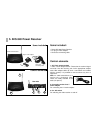
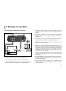
8. Connecting socket for the mains adapter
This is for connecting the mains adapter.
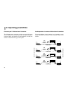
9. A/V cinchinput sockets
1 video, 2 audio input sockets for feeding in the transmission signals.
With adapter cables (2 are included with the system) it is possible to
connect almost any item of equipment.
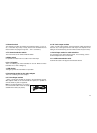
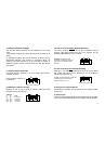
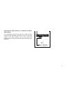
Note: for audio transmissions, it is usual to
use a cinch/cinch cable. These are readily
available in the trade (see picture).
10. AV cinch output sockets
1 video, 2 audio output sockets. These transmit the cable channel that
has been set, or the signal from the video input. This depends on the
setting of the mode button (5) and the remote control unit (see Point 5).
11. Aerial input socket for cable television
For connection to the cable television socket. For connecting, use the
enclosed adapter and the co-axial cable.
12. 2.4 GHz transmission aerial
Transmits the cable or AV signal to the selected channel.