


REQUIREMENTS/SPECIFICATIONS
2-7
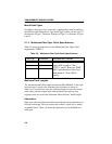
Fiber Optic Budget
The fiber optic delay budget, which determines the fiber optic cable’s
maximum length, should be calculated and taken into consideration in the
network design stage. Fiber optic delay budget is determined by summing
the optical signal loss due to fiber optic cable attenuation, in-line splices,
and fiber optic connectors.
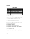
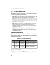
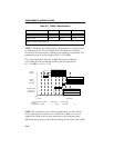
2.1.4 Single Mode Fiber Optic Cable Specifications
Table 2-7 shows specifications for the Single Mode Fiber Optic Cable
supported by TPIM-F3.
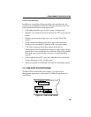
Maximum Trunk Lengths
The maximum trunk cable length between the MicroMMAC-T and other
active devices is equal to the Maximum Drive Distance as shown in
Table 2-7. For passive devices, the combined length of twice the longest
trunk cable plus the longest lobe cable attached to the passive ring segment
must not exceed the Maximum Drive Distance Trunk Length.
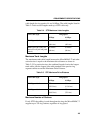
Attenuation
Fiber optic cable must be tested with an attenuation test set adjusted for a
1300 nm wavelength. This test ensures that the cable’s signal loss is within
an acceptable range of 10 dB or less for any given single mode fiber optic
link.
Table 2-7. Single Mode Fiber Optic Cable Specifications
Cable Type Attenuation Maximum Drive Distance
8/125-12/125 µm 10.0 dB or less The max. allowable fiber optic
cable length is 10 km (10936
yards). However, IEEE 802.5
specs allow for a max. of 1 km
(1093.6 yards).