


REQUIREMENTS/SPECIFICATIONS
2-9
Other Considerations
In addition to complying with the preceding cable specifications, the
following recommendations should be followed to minimize errors and
obtain optimum performance from the network:
• UTP cabling should be free of splices, stubs, or bridged taps.
• Maintain a two punch-down block limit between TCU ports and wall
outlets.
• Properly ground metal troughs, ducts, etc. carrying Token Ring
signals.
• Avoid routing Token Ring signals near copper cables that exit a
building or are susceptible to lightning strikes and power surges.
• UTP cables containing Token Ring signals should not be
simultaneously used for applications which may impress high voltages
(greater that 5 volts) with sharp rise or fall times. The noise coupling
from such signals could directly cause errors on the Token Ring
network.
• Lobe lengths between TCU ports and connected devices should not
exceed 100 meters of 22 to 24 AWG wire.
• Wherever possible, use dedicated UTP cable for Token Ring signals.
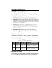
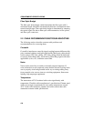
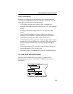
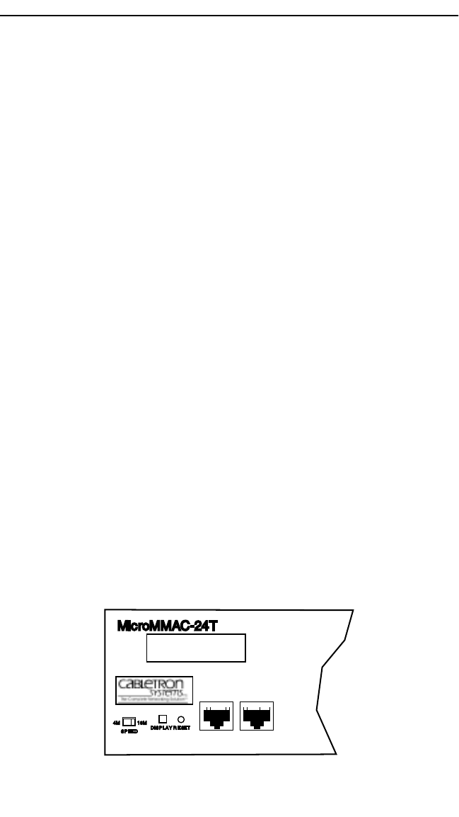
2.3 COM PORT SPECIFICATIONS
The RJ45 COM 1 and COM 2 ports (Figure 2-2) support Local
Management applications. A description of COM port applications is
listed below:
Figure 2-2. COM 1/COM 2 Ports
COM 2
COM 1
TOKEN RING HUB
WITH
LANVIEW®
SUPPORTING 100 OHM UTP CABLE
MicroMMAC-24T
DISPLAY
RESET
SPEED
16M4M