


Connectors, Adapters and Cable Connections
B-8
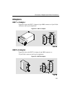
1
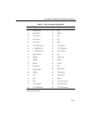
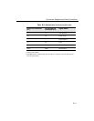
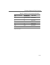
Contacts tied together.
2
120 OHM resistor, 1/2w between pins 10 and 35, 13 and 38, 17 and 42. The resistors
are at P1 end of cable.
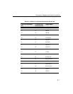
15 17 Clock A
40 35 Clock B
17 5 TX Clock A
42 23
TX Clock B
2
18 18 Test Indicate
37 19, 37
DTE Ground
1
20 10 Local Loop
41 16 Speed Select
45 14 Remote Loop
Shell Shell Shield Braid
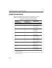
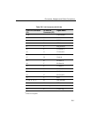
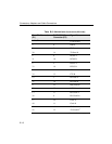
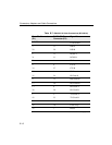
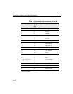
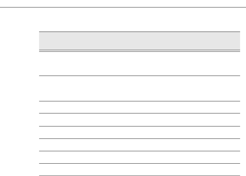
Table B-4. EIA422/V.11/V.36 Cable Connections (BC12H–06)
From Pin Connector
(P1)
To EIA422 Pin
Connector P2)
Signal Name