


B-9
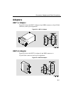
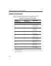
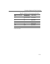
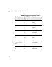
Connectors, Adapters and Cable Connections
1
Contacts tied together.
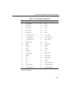
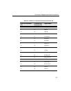
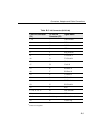
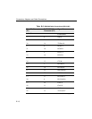
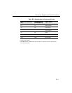
Table B-5: V.35 Connection (BC12G-06)
From Pin Connector
(P1)
To V.35 Pin
Connector (P2)
Signal Name
1, 26 –
Code Ground
1
4EDSR A
6 F DCD/I A
9DCTS A
11 J Ring Indicate
21 Y TX Clock A
46 A TX Clock B
22 U Clock A
47 W Clock B
23 R RX Data A
48 T RX Data B
24 P TX Data A
49 S TX Data B
25 V RX Clock A
50 X RX Clock B
32 C RTS
12, 29, 31, 34, 37 B
DTE Ground
1
44 H DTR
Shell Braid Strap Overall Cable Shield
20 K Local Loop