


Chapter 3: Installation
3-2 6E122-26, 6E132-25, 6E123-26 and 6E133-25 User’s Guide
3.3 6E12X-26 AND 6E13X-25 OPTIONS
If the 6E12X-26 is to be installed with an optional Fast Ethernet Interface
Module, refer to Appendix C for installation instructions. The installation
instructions for the HSIMs available for the 6E13X-25 are located in the
associated user’s guide.
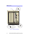
3.4 INSTALLING THE 6E12X-26 AND 6E13X-25 INTO
THE 6C105 CHASSIS
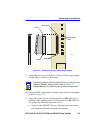
The 6E12X-26 and 6E13X-25 can be installed in any of the 5 slots that
are available. To install a module, proceed as follows:
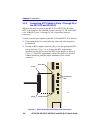
1. Remove the blank panel covering the slot in which the module will be
installed. All other slots must remain covered to ensure proper airflow
and cooling. (Save the blank plate in the event you need to remove the
module.)
2. Carefully remove the module from the shipping box. (Save the box
and packing materials in the event the module must be reshipped.)
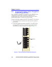
3. Locate the antistatic wrist strap shipped with the 6C105 chassis.
Attach the strap to your wrist and plug the cable from the antistatic
wrist strap into the ESD grounding receptacle at the upper right corner
of the 6C105.
NOTE
Install any optional equipment before proceeding to
Section 3.4.
!
CAUTION
Failure to observe static safety precautions could cause
damage to the 6E12X-26 and 6E13X-25. Follow static safety
handling rules and properly wear the antistatic wrist strap
provided with the 6C105 chassis.
!
CAUTION
Do not cut the non-conductive bag to remove the module.
Damage could result from sharp objects contacting the board
or components.