


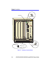
Chapter 3: Installation
3-8 6E122-26, 6E132-25, 6E123-26 and 6E133-25 User’s Guide
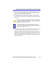
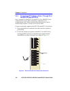
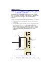
3.5.2 Connecting UTP Cables to Ports 1 Through 24 of
the 6E133-25 and 6E123-26
When facing the front panel of the 6E133-25 or 6E123-26, the upper
RJ21 is the connector for 10BASE-T ports 1 through 12. The lower RJ21
is for 10BASE-T ports 13 through 24. All 24 ports have internal
crossovers.
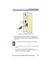
Connect a twisted pair segment to the 6E133-25 and 6E123-26 as follows:
1. Ensure that the device connected to the other end of the segment is
powered ON.
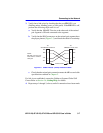
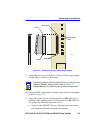
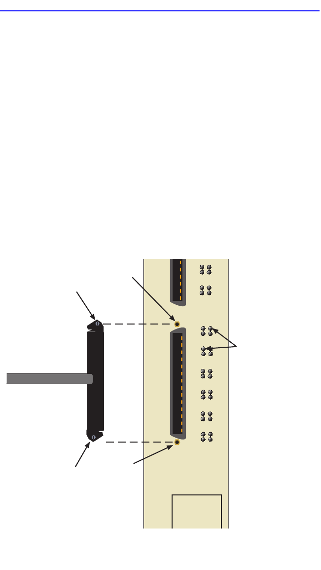
2. If using an RJ21 straight connector, plug it into the appropriate RJ21
port as shown in Figure 3-4 or, if using the RJ21 angle adapter
supplied with the device, insert the RJ21 angle adapter as shown in
Figure 3-5. The RJ21 angle adapter allows the cable to be inserted
without interfering with the proper attachment of the second
connector.
.
Figure 3-4 6E133-25 and 6E123-26 Twisted Pair Connection
1413
910
11 1 2
15 16
17 18
19 20
21 22
23 24
RX (Receive)
LED
207603
Screw
Screw Hole
Screw Hole
Screw
24
13
1