


Appendix C: Mode Switch Bank Settings and Optional Installations
C-2 6E122-26, 6E132-25, 6E123-26 and 6E133-25 User’s Guide
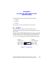
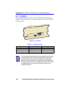
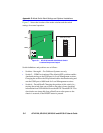
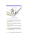
Figure C-1 shows the location of the mode switches and the switch
settings for normal operation.
Figure C-1 6E12X-26 and 6E13X-25 Mode Switch
Location/Component Layout
Switch definitions and positions are as follows:
• Switches 1 through 4 – For Cabletron Systems use only.
• Switch 5 – COM Port Autobaud. The default (OFF) position enables
Autobaud sensing on the COM port for Local Management sessions.
Changing the switch to the ON position disables Autobaud sensing and
sets the COM port to 9600 baud for Local Management sessions.
• Switch 6 – Forced BootP. Changing the position of this switch (i.e.,
moving the switch from one position to the other) clears download
information from NVRAM and forces the 6E12X-26 and 6E13X-25 to
download a new image file from a BootP server after power to the
chassis is restored, or the RESET button is pressed.
Flash
DRAM
MODE SWITCH BANK
1
2
3
4
5
6
7
8
OFF ON