


Connecting to the Network
6E122-26, 6E132-25, 6E123-26 and 6E133-25 User’s Guide 3-9
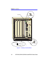
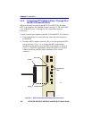
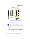
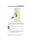
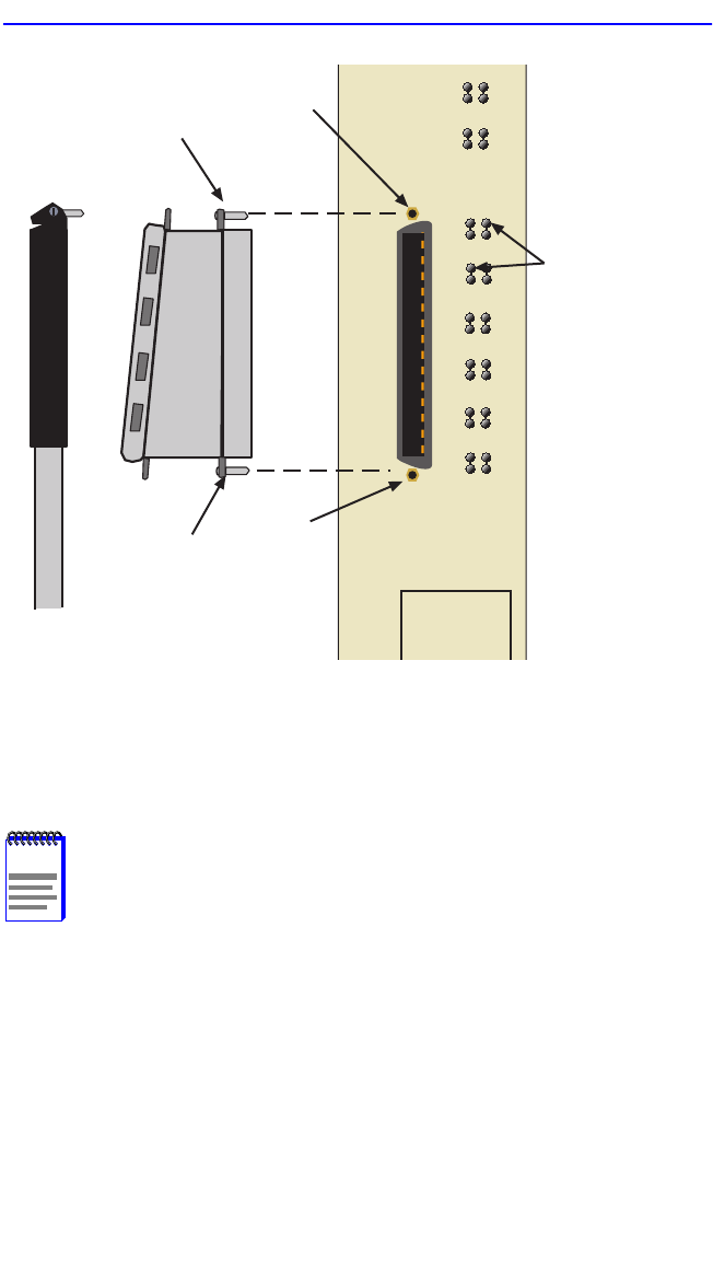
Figure 3-5 Connection Using the RJ21 Angle Adapter
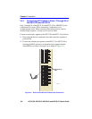
3. Tighten the two screws on the RJ21 connector or RJ21 angle adapter,
as applicable, to secure it to the module.
4. If using the RJ21 angle adapter, plug the 25 pair cable into the adapter
as shown in Figure 3-5.
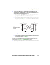
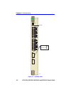
5. Verify that a link exists by checking that the port RX LEDs are on
(flashing amber, blinking green, or solid green). If the RX LEDs are
off, perform the following steps until it is on:
a. Verify that the 10BASE-T device at the other end of the twisted
pair segment is ON and connected to the segment.
NOTE
The cable pinouts for a 25 pair cable (RJ21) can be found in the
Cabletron Systems
Cabling Guide
. Refer to Section 1.7,
Related Manuals, for details on how to obtain this document.
1413
910
11 1 2
15 16
17 18
19 20
21 22
23 24
RX (Receive)
LED
207603
Screw
Screw Hole
Screw
Screw Hole