6E122-26, 6E132-25, 6E123-26 and 6E133-25 User’s Guide 4-1
CHAPTER 4
TROUBLESHOOTING
This chapter provides information concerning the following:
• Using the LANVIEW diagnostic and status monitoring system
• Troubleshooting network and module operational problems
• Using the RESET button
4.1 USING LANVIEW
The 6E12X-26 and 6E13X-25 use Cabletron Systems built-in visual
diagnostic and status monitoring system called LANVIEW. The
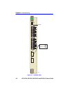
LANVIEW LEDs (Figure 4-1) allow quick observation of the network
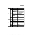
status to aid in diagnosing network problems. Refer to Table 4-1 for a
description of the LEDs.
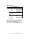
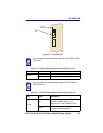
For a functional description of the LANVIEW LED on the optional Fast
Ethernet Interface Module (FE-100TX), refer to Section 4.2.
All LEDs for the High Speed Interface Module (HSIM) are located on the
HSIM and are described in the associated HSIM user’s guide.
NOTE
The four interface modules covered in this manual all share the
same LANVIEW LEDs.
NOTE
The terms flashing, blinking, and solid used in the LED
definition tables of this chapter indicate the following:
Flashing indicates an irregular LED pulse.
Blinking indicates a steady LED pulse.
Solid indicates a steady LED light. No pulsing.


