


Connecting to the Network
Installation 3-5
.
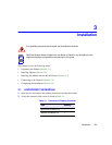
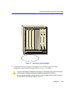
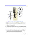
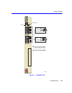
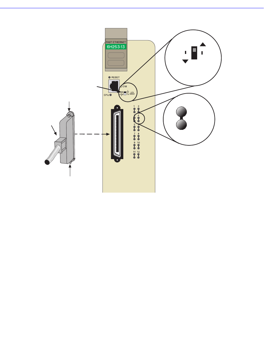
Figure 3-2 Connecting a Twisted Pair Segment to the SmartSwitch
3. Verify that a link exists by checking that the port RX (Receive) LED is ON (flashing amber,
blinking green, or solid green). If the RX LED is OFF and the TX (Transmit) LED is not
blinking amber, perform the following steps until it is on:
a. Verify that the LED mode switch located near the COM port of the module is in the UP
position (RX and TX LED indicators).
b. Verify that the cabling being used is Category 5 UTP with an impedance between 85 and
111 ohms. If the port is to operate at 100 Mbps, category 5 cabling must be used.
c. Verify that the device at the other end of the twisted pair segment is on and properly
connected to the segment.
d. Verify that the RJ21 connectors on the twisted pair segment have the proper pinouts (see
the Cabletron Systems Cabling Guide) and check the cable for continuity. Typically, a
crossover connection is used between a switching or hub device and an end user
(computer). A straight-through connection is used between hub devices.
RX LED
TX LED
LED Mode Switch
DPX
SPD
RX
TX
LED MODE Switch
in RX-TX position
RJ21
Screw
Screw