


Setting the Mode Switches
B-2 Switch Settings, Upgrades, and Installations
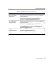
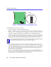
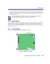
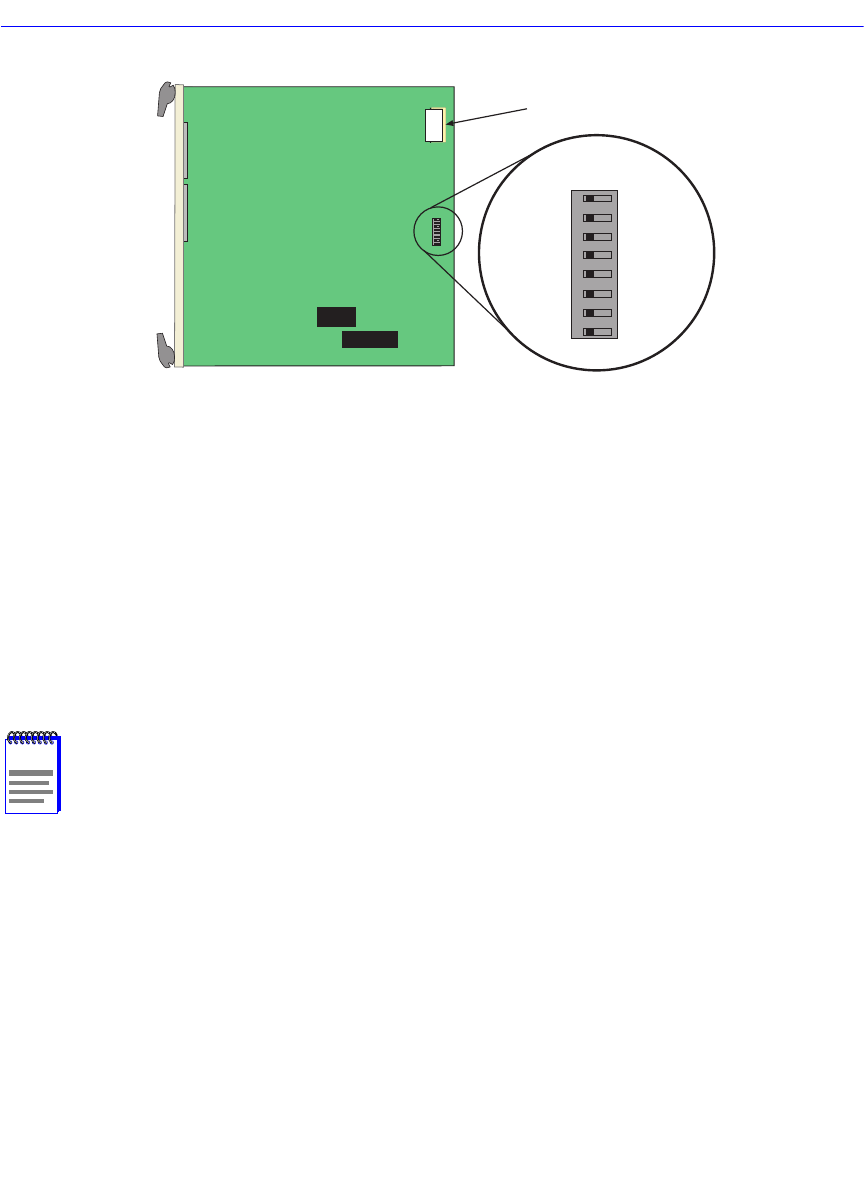
Figure B-1 Module Mode Switch Location/Component Layout
Switch definitions and positions are as follows:
• Switches 1 through 4 – For Cabletron Systems use only.
• Switch 5 – COM Port Autobaud. The default (OFF) position enables Autobaud sensing on the
COM port for Local Management sessions. Changing the switch to the ON position disables
Autobaud sensing and sets the COM port to 9600 baud for Local Management sessions.
• Switch 6 – Forced BootP. Changing the position of this switch (i.e., moving the switch from one
position to the other) clears download information from NVRAM and forces the SmartSwitch
to download a new image file from a BootP server after power to the chassis is restored.
• After changing the position of switch 6 and restarting the module, the module requests a new
image download until they either receive a new image or the RESET button on the front panel
is pressed. When the RESET button is pressed, the module continues trying to contact a BootP
server, but will time out in approximately one minute. If the module times out, the image is
downloaded from its FLASH memory.
• Switch 7 – Clear NVRAM. Changing the position of this switch resets NVRAM on the next
power up. ALL user entered parameters, such as IP addresses, subnet masks, SNMP traps, and
switching functions are restored to their factory default settings.
NOTE
After changing the position of switch 6, DO NOT reapply power to the chassis until there
is a station acting as a BootP server, which contains the image file.
DRAM
MODE SWITCH
1
2
3
4
5
6
7
8
OFF ON
2159_34