


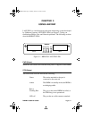

CHAPTER 2:
INSTALLATION
Page 2-8
BRIM-F6 User’s Guide
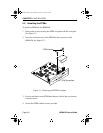
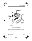
9. Press down firmly on the back of the BRIM until the pins slide all the
way into the connector holes.
Note:
Make sure that the standoffs align with the standoff screw holes.
10. Reinstall the coverplate/faceplate screws and standoff screws.
Note:
Faceplate and support post screws are provided both on the hub and
in the BRIM package.
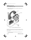
The BRIM-F6 requires a special 24 pin ribbon connector in addition to
the standard 96 pin BRIM connector. This ribbon connector allows the
BRIM-F6 to use in-line filtering functionality.
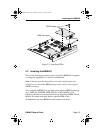
To install the BRIM-F6 ribbon cable:
1. Insert one ribbon cable connector into the ribbon cable jack on the
BRIM. (See Figure 2-4.)
Caution:
The ribbon cable connector only fits into the ribbon cable jack
one way. Fit the tab on the connector into the groove in the jack for correct
cable orientation.
2. Press down on the connector until the clips on the jack snap into a
vertical locked position.
3. Insert the remaining ribbon cable connector into the ribbon cable jack
in the hub.
4. Press down on the connector until the clips on the jack snap into a
vertical locked position.
After returning the cover, returning power to your device, and
reconnecting to the network, your BRIM-F6 is now ready for operation.
BRIM-F Book Page 8 Monday, January 29, 1996 9:26 AM