


ANSI Standard X3T9.5
BRIM-F6 User’s Guide Page A-5
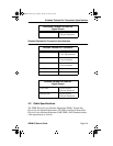
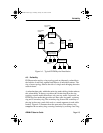
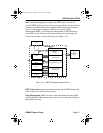
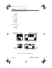
Figure A-3. FDDI Structure and the OSI Network Model
The PMD standard establishes the physical characteristics of the network
connection, including the fiber optic transmitter power levels, receiver
sensitivity, the fiber optic cable type, the type of connectors, and
acceptable losses between nodes. The PMD converts the optically
encoded information that it receives to electrically encoded information
and presents it to the PHY sublayer. The layers reverse this process when
transmitting information.
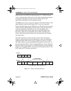
The PHY entity implements the physical layer protocol. The PHY
receives data frames from the MAC as a series of 4-bit symbols and
encodes each 4-bit MAC symbol as a 5-bit symbol for transmission. This
encoding occurs to ensure each symbol has at least two bit transitions for
bit-cell synchronization at the remote receiver. Decoding reverses this
process for the received frames.
Data Link
Physical
MAC
PHY
PMD or SMF-PMD
Application
Presentation
Session
Transport
Network
Data Link
Physical
SMT
• Fault Isolation and
Recovery
• Power Levels
• Connector Types
• Transmitter
• Receiver
• Symbol Coding/Decoding
• Clock Rate
• Symbol Framing
• Medium Addressing
• Data Checking
• Data Framing
Media Access Control
Physical Layer Protocol
Physical Layer Medium Dependent
Station Management
• Optical Interface
• Station Configuration
• Scheduling Procedures
LLC
BRIM-F Book Page 5 Monday, January 29, 1996 9:26 AM