


Appendix A: WPIM Cable Specifications
A-8 CSX200 Installation Guide
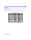
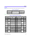
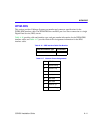
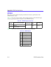
X.21
Table A-12 shows the connector number, cable assembly description, and connector type.
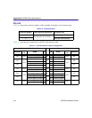
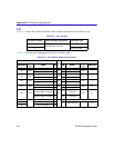
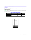
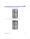
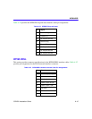
Table A-13 provides pin assignments for the X.21 interface cable.
Table A-12 X.21 Interface
Connector Number Cable Assembly Description Connector Type
1
EIA-530A ALT A to X.21
Sub DB 26-pin male
2 DB-15 pin male
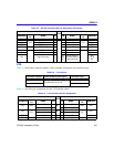
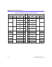
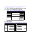
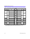
Table A-13 X.21 Interface Cable Pin Assignment
Connector 1 EIA-530A ALT A
PAIR
Connector 2 X.21
MNEMONIC
DIRECT
TO
NAME PIN PIN NAME
DIRECT
TO
MNEMONIC
BA DCE
Transmit Data A 2
A
2 Transmit A
DCE T
Transmit Data B 14 9 Transmit B
BB DTE
Receive Data A 3
B
4 Receive A
DTE R
Receive Data B 16 11 Receive B
CB DTE
Clear to Send A 5
C
5 Indication A
DTE I
Clear to Send B 13 12 Indication B
CA DCE
Request to Send A 4
D
3 Control A
DCE C
Request to Send B 19 10 Control B
DB DTE
Transmit Signal Timing A
Receive Signal Timing A
17
15
E
6
Signal Element
Timing A
DTE S
Transmit Signal Timing B
Receive Signal Timing B
9
12
13
Signal Element
Timing B
SHIELD 1 DRAIN
AC DTE Common 7
8 Signal Ground G
AB DCE Common 23