


Connecting A Fiber Optic Link Segment
EMC39-12 User’s Guide Page 3-3
3.2 CONNECTING A FIBER OPTIC LINK SEGMENT
When connecting a fiber optic link segment to the EMC39-12 keep the
following in mind:
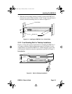
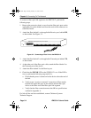
• ST connectors attach to ST ports much like BNC connectors
attach to BNC ports. Insert the connector into the port with the
alignment key on the connector inserted into the alignment slot on
the port. The connector is then turned to lock it down.
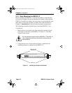
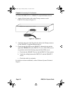
• The physical communication link consists of two strands of fiber
optic cabling: the Transmit (TX) and the Receive (RX). The
transmit strand from the applicable port on the module will be
connected to the Receive port of a fiber optic Ethernet device at the
other end of the segment. For example, TX of the applicable port
on the module will go to RX of the other fiber optic device. The
Receive strand of the applicable port on the module will be
connected to the Transmit port of the fiber optic Ethernet device.
For example, RX of the applicable port on the module will go to
TX of the other fiber optic device.
We recommend that you label the fiber optic cable to indicate which
fiber is Receive and which is Transmit. When you buy fiber optic
cable from Cabletron Systems, it is labeled so that at one end of the
cable, one fiber is labeled 1, and the other fiber is labeled 2. This
pattern is repeated at the other end of the cable. If you did not purchase
your cable from Cabletron Systems, be sure you label your cable as
described above.
!
CAUTION
Do not touch the ends of the fiber optic strands, and do not let
the ends come in contact with dust, dirt, or other contaminants.
Contamination of the ends can cause problems in data
transmissions. If the ends become contaminated, clean them
with alcohol using a soft, clean, lint free cloth.
emc39bk Page 3 Monday, February 12, 1996 4:21 PM