


Chapter 3: Connecting To The Network
Page 3-4 EMC39-12 User’s Guide
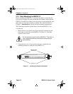
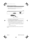
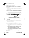
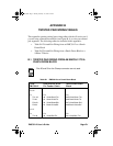
To connect a fiber optic link segment to the EMC39-12, perform the
following steps:
1. Remove the protective plastic covers from the fiber optic ports on the
applicable port on the module and from the ends of the connectors on
each fiber strand.
2. Attach the fiber labeled 1 to the applicable Receive port, labeled RX,
on the module. See Figure 3-2.
Figure 3-2 Connecting a Fiber Link to the EMC39-12
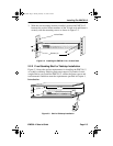
3. Attach the fiber labeled 2 to the applicable Transmit port labeled TX,
on the module.
4. At the other end of the fiber optic cable, attach the fiber labeled 1 to
the Transmit port of the device.
5. Attach the fiber labeled 2 to the Receive port.
6. Check that the FOLNK LED on the ECM39-12 is on. If the LED is
not on, perform the following steps until it is:
a. Check that the power is turned on for the device at the other end of
the link.
b. Verify proper “receive to transmit” connection of fiber strands
between the applicable port on the module and the fiber optic
device at the other end of the fiber optic link segment.
c. Verify that the fiber connection meets the dB loss specifications
outlined in Appendix A.
If a link still has not been established, contact Cabletron Systems
Technical Support.
EMC39-12 Ethernet Media Converter WITH LANVIEW
TPLINK
XMT
RCV
FOLNK
12 11 10 9 8 7 6 5 4 3 2 1
PWR
12 10 9
87
6543
21
RX
TX
RX
TX
RX
TX
RX
TX
RX
TX
RX
TX
RX
TX
RX
TX
RX
TX
RX
TX
RX
TX
RX
TX
11
emc39bk Page 4 Monday, February 12, 1996 4:21 PM