


3-15
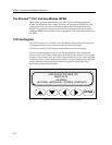
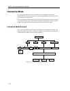
Interactive Mode
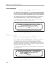
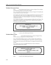
The Power Screen
Select <PWR> from the System Screen, as shown in Figure 3-15, to access
information about the chassis power supply configuration.
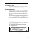
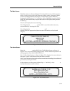
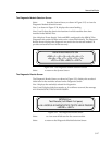
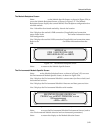
Line 1 of the Power Screen, as shown in Figure 3-16, displays the number of
power supplies currently configured and the availability of power redundancy.
Lines 2 and 3 display the power supply status as either ON, OFF DUE TO
MANAGEMENT, or FAULT.
Line 4 is used to access information about a specific power supply module by
selecting a power supply number.
Figure 3-16. The Power Screen
Select <EXIT> to return to the System Screen.
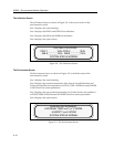
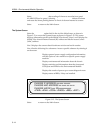
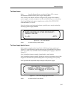
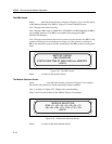
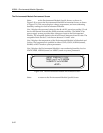
The Power Supply Specific Screen
Select a power supply number from line 4 of the Power Screen, as shown in
Figure 3-16, to learn about a specific power supply in the MMAC-Plus chassis.
There is an LCD screen available for each installed power supply, as shown in
Figure 3-17.
Line 1 identifies the power supply selected and its serial number.
Line 2 identifies the power supply’s hardware revision, firmware revision of the
diagnostic controller and power loading factor as a percentage of its capacity.
Line 3 provides the input and output voltages of the power supply.
Figure 3-17. The Power Supply Specific Screen
Select <EXIT> to return to the Power Screen.
STATUS 1 ON 2 ON
<1>
SUPPLIES INSTALLED 2 PWR REDUNDANCY
<EXIT><2>
HW REV xxx FW REV x.xx.xx LOAD xxx%
<EXIT>
PWR SUPPLY 1 SN xxxxxxxxxxxx
PWR IN 110V PWR OUT 57.1V 5.1V 3.3V