


9C300-1 Environmental Module Operation
3-20
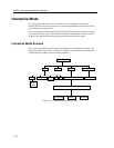
The Module Environment Screen
Select <ENV> at the Module Specific Screen, as shown in Figure 3-24, to display
environmental parameters for the specific module.
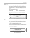
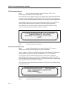
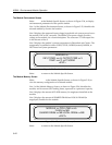
Line 1 of the Module Environment Screen, as shown in Figure 3-25, identifies the
selected module by chassis slot location.
Line 2 displays the measured input voltage from the 48 volt system power bus to
the module’s DC-to-DC converter. The MMAC-Plus power supply provides
voltage to the module via a chassis backplane. The converter’s 5 volt output line
is also shown on line 2.
Line 3 displays the module’s current temperature in Fahrenheit and Celsius. The
temperature is qualified as either COLD, COOL, NORM (normal), WARM, or
HOT based on system parameters.
Figure 3-25. The Module Environment Screen
Select <EXIT> to return to the Module Specific Screen.
The Module Memory Screen
Select <MEMORY> at the Module Specific Screen, as shown in Figure 3-24, to
view the memory configuration of a selected module.
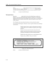
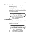
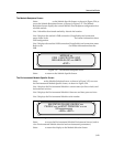
Line 1 of the Module Memory Screen, as shown in Figure 3-26, identifies the
module, and its current CPU loading factor, expressed as a percent of capacity.
Line 2 displays the amount of FLASH memory (in megabytes) installed on the
module.
Line 3 displays the amount of SHARED DRAM and LOCAL DRAM (in
megabytes) installed on the module.
Figure 3-26. The Module Memory Screen
Select <EXIT> to return to the Module Specific Screen.
<EXIT>
MODULE xx
TEMP: xxx°F, xx°C NORM
INPUT PWR: xx.xV, OUTPUT PWR x.xV
FLASH xx MB
<EXIT>
MODULE xx, CPU LOAD xxx%
SHARED DRAM xx MB LOCAL DRAM xx MB