


3-17
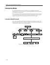
Interactive Mode
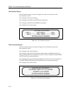
The Diagnostic Module Selection Screen
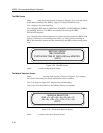
Select <DIAGS> from the System Screen, as shown in Figure 3-15, to view the
Diagnostic Module Selection screen.
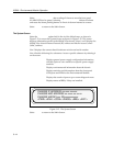
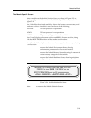
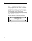
Line 1, as shown in Figure 3-20, displays the screen heading.
Lines 2 and 3 show the chassis slot locations in which modules have been
installed in the MMAC-Plus.
Line 4 displays Power Supply Units and BBUs configured in the MMAC-Plus.
Diagnostic test results for these units can be viewed individually. The Diagnostic
Results Screen displays the diagnostic test results for the selected modules. It
provides an itemized list of failed tests only.
Figure 3-20. The Diagnostic Module Selection Screen
Select <EXIT> to return to the System Screen.
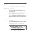
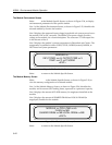
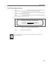
The Diagnostic Results Screen
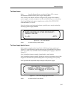
The Diagnostic Results Screen, as shown in Figure 3-21, displays the results of
failed tests for the modules selected on the Diagnostic Screen.
Line 1 displays the module(s) selected for diagnostics.
Lines 2 and 3 display failed test results; or, if no failures occurred, the message
ALL DIAGNOSTICS TESTS HAVE PASSED.
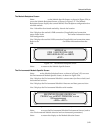
Figure 3-21. The Diagnostic Results Screen
Select <MORE> to view more failed tests for the current module.
Select <EXIT> to return to the Diagnostic Module Selection Screen.
<EM> <1> <2> <3> <4> <5> <6> <7>
<PS1> <PS2> <BBU1> <EXIT>
VIEW DIAG RESULTS ON
<8><9> <10> <11> <12> <13> <14>
Test Results (Left Blank if all pass)
<MORE> <EXIT>
MODULE xx
or ALL MODULE DIAGNOSTICS TESTS HAVE PASSED