


Connecting to the Network
HSIM-FE6 User’s Guide 2-11
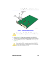
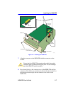
4. Verify that a link exists by checking that the port receive LED is ON
(flashing amber, blinking green, or solid green). If the receive LED is
OFF and the transmit LED is not blinking amber, perform the
following steps until it is ON:
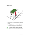
a. Check that the power is turned on for the device at the other end of
the link.
b. Verify proper crossover of fiber strands between the port on the
HSIM-FE6 and the fiber optic device at the other end of the fiber
optic link segment.
c. Verify that the fiber connection meets the dB loss specifications
outlined in Appendix B.
If a link has not been established, refer to Chapter 3, LANVIEW LEDs,
before contacting the Cabletron Systems Global Call Center. Refer to
Section 1.5 for details.
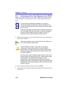
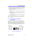
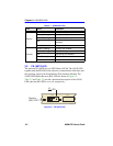
2.4.2 Connecting a Twisted Pair Segment
to the FE-100TX
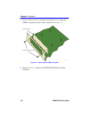
An FE-100TX has an internal crossover switch. When connecting a
workstation, use a straight-through cable and set the FEPIM crossover
switch shown in Figure 2-5 to the crossed over position marked with X.
When connecting networking devices, such as another bridge, repeater, or
router, use a straight-through cable and set the FEPIM crossover switch
shown in Figure 2-5 to the straight-through position, marked with =.
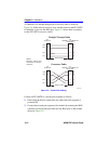
Figure 2-5 FE-100TX Crossover Switch
FE-100TX
10
100
=
x
fecrossover
Position =
(not crossed over)
1. TX+
2. TX-
3. RX+
4. NC
5. NC
6. RX-
7. NC
8. NC
Position X
(crossed over)
1. RX+
2. RX-
3. TX+
4. NC
5. NC
6. TX-
7. NC
8. NC