


Chapter 2: Installation
2-12 HSIM-FE6 User’s Guide
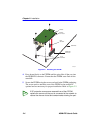
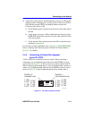
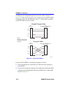
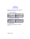
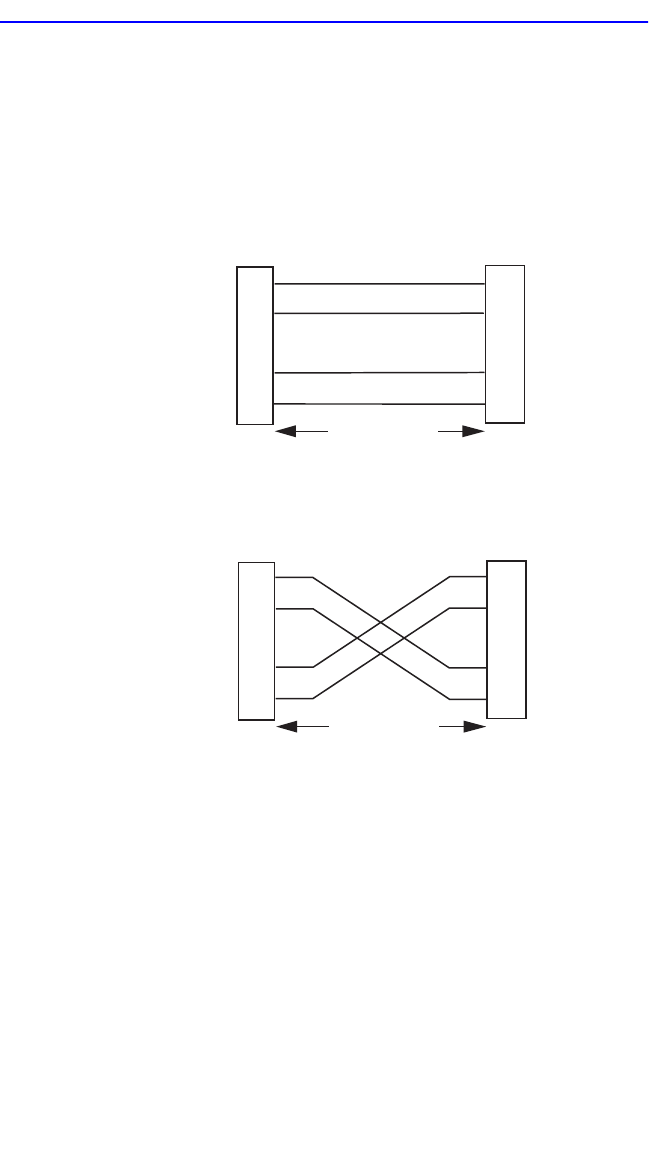
A schematic of a straight-through and a crossover cable is shown in
Figure 2-6. If the wires do not cross over, use the switch on the FE-100TX
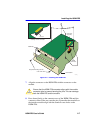
to internally cross over the RJ45 port. Figure 2-5 shows how to properly
set the FE-100TX crossover switch.
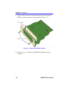
Figure 2-6 Twisted Pair Cabling
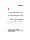
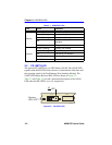
Connect an FE-100TX to a twisted pair segment as follows:
1. Ensure that the device connected to the other end of the segment is
powered ON.
2. Connect the twisted pair segment to the module by inserting the RJ45
connector on the twisted pair cable into the RJ45 port on the module
shown in Figure 2-5.
TX+
TX–
RX+
RX– 2
1
3
6
TX+
TX–
2
1
3
6
NOTE:
RX+/RX– and TX+/TX–
must share a common
color pair.
TO
RJ45 Port
25041-08
RJ45 to RJ45
RX+
RX–
TX+
TX–
RX+
RX– 2
1
3
6
TO
10BASE-T or 100BASE-TX
Device Port
TX+
TX–
2
1
3
6
RJ45 to RJ45
RX+
RX–
TO
RJ45 Port
Straight-Through Cable
Crossover Cable
TO
10BASE-T or 100BASE-TX
Device Port