


Section 5. Programming the Datalogger
5-23
– see ‘SDM Port’ in Section 1 for details. This should be connected to control port
8 for this example.
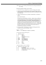
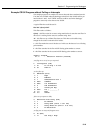
A typical filter that could be used is as follows:
fltst 200 "t[data]A5xff"
This filter works as follows:
t[data] – this filter waits for an exact string match before it starts the next filter. In
this case it is waiting for the sensor to send the string ‘data’.
A5 – this filter sets up a 250ms filter time out. This time out should be long
enough for the sensor to transmit all of its data.
x – this filter marks the start of the data set. In this case the data set is two floating
point numbers.
f – this filter searches for the first ASCII floating point number to convert.
f – this filter searches for the second ASCII floating point number to convert.
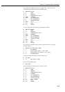
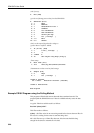
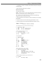
*Table 1 Program
01: 2 Execution Interval (seconds)
;set control port 8 to i/p so it can be used as an interrupt
1: Set Port(s) (P20)
1: 8999 C8..C5 = input/nc/nc/nc
2: 9999 C4..C1 = nc/nc/nc/nc
;do filter setup only if flag one is clear
2: If Flag/Port (P91)
1: 21 Do if Flag 1 is Low
2: 30 Then Do
;set up string filter
3: SDM-SIO4 (P113)
1: 1 Reps
2: 0 Address
3: 1 Send/Receive Port 1
4: 2054 Command
5: 9200 1st Parameters
6: 0 2nd Parameters
7: 0 Values per Rep
8: 0 Loc [ _________ ]
9: 1.0 Mult
10: 0.0 Offset
;delay required by filter setup command
4: Excitation with Delay (P22)
1: 1 Ex Channel
2: 0 Delay W/Ex (units = 0.01 sec)
3: 1 Delay After Ex (units = 0.01 sec)
4: 0 mV Excitation
;set flag one high so the filter set-up is only done once
5: Do (P86)
1: 11 Set Flag 1 High