


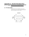


Appendix A. CS I/O 9 Pin Serial Port
A-2
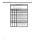
TABLE A-1. Pin Description
ABR = Abbreviation for the function name.
PIN = Pin number.
O = Signal Out of the datalogger to a peripheral.
I = Signal Into the datalogger from a peripheral.
PIN ABR I/O Description
1 5V I 5 VDC supply. Not used.
2 SG Signal Ground: Provides a power return for pin 1
(5V), and is used as a reference for voltage levels.
3 RING O Ring: Raised by the modem to put the datalogger
in the telecommunications mode.
4 RXD O Receive Data: Serial data transmitted by the
modem are transmitted on pin 4.
5 ME I Modem Enable: A logic high internally switches
power to the modem. A logic low internally
powers down the modem.
6 SDE I Synchronous Device Enable: A logic high disables
communication with the modem, without removing
power or changing the modem’s mode.
7Clock/
HS
I/O Clock/Handshake: Used with the SDE and TXD
lines to communicate with devices that address it.
8 TE I +12 VDC power supply.
9 TXD I Transmit Data: Serial data are transmitted from
the datalogger to the modem on pin 9; logic low
marking (0V) logic high spacing (5V) standard
asynchronous ASCII, 8 data bits, no parity, 1 start
bit, 1 stop bit, 300, 1200, 9600, 76,800 baud (user
selectable).