


COM300 Voice Communication Modem
4
SE
DIFF
G
GH L
12
1
AG H L AG H L AG E1 AG E2 G
34
2
56
3
SE
DIFF
G
GH L
78
4
AG H L AG H L AG E3 AG G G
910
5
11 12
6
P1 G P2 G C8 C7 C6 C5 C4 C3 C2 C1 G 12V 12V
SDM
5V 5V G G
SW 12V
SW 12V CTRL
Logan, Utah
G 12V
G 12V
POWER
IN
CR10X WIRING PANEL
MADE IN USA
WIRING
PANEL NO.
EARTH
GROUND
CS I/O
CAMPBELL
SCIENTIFIC
INC.
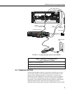
COM300
VOICE SYNTHESIZER
S/N
0002
MADE IN USA
GND
RING
TIP
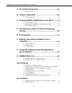
Burial Phone Cable
Blue = Ring
Blue/White = Tip
To Earth Ground
Phone Line
Transient Protector
(Model 6362 or 2372-01)
SC12 Cable
Complies with Part 68, FCC rules. FCC Registration No. B9QUSA-75378-MM-T
Ringer Equivalence 0.5A. Required Connector USOC RJ11C.
This equipment complies with the requirements in Part 15 of FCC Rules for Class A
computing device. Operation of this equipment in a residential area may cause
unacceptable interference to radio and TV reception requiring the operator to take
whatever steps are necessary to correct the interference.
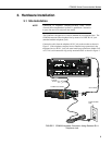
FIGURE 3. COM300 Hardware Connection to CR10X Using Surge
Protection Device (No Standard RJ11 Connection Available)
3.2 Properly Grounding the COM300 System
Connect the green 14 awg grounding wire (provided with the COM300) to the
grounding terminal (GND) on the COM300 and to the enclosure’s earth ground
connection. If the site does not have a grounded enclosure, connect the ground
wire directly to an earth ground connection. The datalogger ground should also
be tied to the earth ground.
The modem must be grounded for its transient protection to
work.
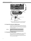
3.3 Powering the COM300 Modem
More recent Campbell Scientific dataloggers provide 12 VDC power on pin 8
of the CS I/O 9 pin connector. For dataloggers that do not provide 12 VDC on
the datalogger's CS I/O 9 pin connector, 12 VDC and ground must be
connected via the green power connector on the side of the COM300 (refer to
Figure 4). Table 1 lists the Campbell Scientific dataloggers that require direct
12 VDC connection to the COM300.
CAUTION