


COM300 Voice Communication Modem Table of Contents
ii
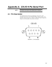
A. CS I/O 9 Pin Serial Port..........................................A-1
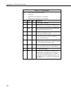
A.1 Pin Description.................................................................................... A-1
B. Theory of Operation ...............................................B-1
B.1 Theory of Operation ............................................................................ B-1
C. Changing RAM or PROM Chips in the CR10 ........C-1
C.1 Disassembling the CR10...................................................................... C-1
C.2 Installing New RAM Chips in CR10s with 16K RAM........................ C-1
C.3 Installing New PROM ......................................................................... C-2
D. FCC Warning to Users of Class A Computing
Devices ...................................................................D-1
E. IC Information ......................................................... E-1
F. Reading Voice Code Information from a
*.DLD File................................................................ F-1
F.1 Typical Voice Code .............................................................................. F-1
F.2 Callback Code.......................................................................................F-2
F.3 Security Enabled ...................................................................................F-3
G. Using P80 to Redirect Final Storage Data to
Input Locations ......................................................G-1
H. COM300 Word List .................................................H-1
H.1 COM300 Word List - Numerical Order .............................................. H-1
H.2 COM300 Word List - Alphabetical Order........................................... H-4
List of Figures
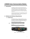
1. COM300 Voice Synthesizer Modem ......................................................... 1
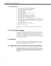
2. COM300 Hardware Connection Using Standard RJ11 Telephone Jack .... 3
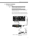
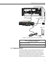
3. COM300 Hardware Connection to CR10X Using Surge
Protection Device...................................................................................... 4
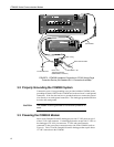
4. Providing Alternate Power to the COM300 ............................................... 5
A-1 9 Pin Connector................................................................................... A-1
C-1 Disassembling CR10 ........................................................................... C-2
C-2 Jumper Settings for Different RAM Configurations............................ C-3
List of Tables
1. Dataloggers that Require Direct 12 VDC Connection to COM300 ........... 5
A-1 Pin Description.................................................................................... A-2