SDM-SW8A Switch Closure Input Module
Instruction 102 is not contained in all CR10 or 21X PROMS. To
verify that the datalogger contains the Instruction, enter 102 into
a datalogger Programming Table. If the Instruction is accepted,
the PROM contains the Instruction.
NOTE
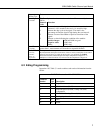
Repetitions (Reps, Parameter 1) specifies the number of SW8A channels to
read. Parameter 2 is the address of the first SW8A. If more Reps are
requested than exist in one module, the datalogger automatically increments
the address and continues to the next SW8A. The address settings for the
SW8As must be sequential. For example, assume two SW8As with addresses
of 22 and 23 are connected, and 12 Reps are requested. Eight channels from
the first SW8A and the first four channels from the next will be read.
Only one Function Option (Parameter 3) may be specified per Instruction. If
all four functions are desired, four Instructions must be entered in the
datalogger program.
Function Option 0 provides the state of the signal at the time 102 is executed.
A 1 or 0 corresponds to high or low states, respectively.
Function Option 1 provides signal duty cycle. The result is the percentage of
time the signal is high during the sample interval.
Function Option 2 provides a count of the number of positive transitions of
the signal.
Function Option 3 provides the signature of the SW8A PROM. A positive
number (signature) indicates the PROM and RAM are good, a zero (0)
indicates bad PROM, and a negative number indicates bad RAM. Function
Option 3 is not used but is helpful in "debugging." Only one Rep is required
for Option 3.
Parameter 4 specifies the first SW8A channel to be read (1..8). One or more
sequential channels are read depending on the Reps. To optimize program
efficiency, the sensors should be wired sequentially.
Data are stored in sequential datalogger input locations, starting at the location
specified in Parameter 5.
The number of input locations consumed is equal to the number of Reps.
The scaling multiplier and offset (Parameters 6 and 7) are applied to all
readings. Enter 1 for the multiplier if no scaling is desired.
If the SW8A does not respond, -99999 is loaded into input locations.
Modules which do not respond when addressed by the datalogger are possibly
wired or addressed incorrectly. Verify that the address specified in Parameter
2 corresponds to the jumper setting and that all connections are correct and
secure.
An example program for reading state, duty cycle, and counts of all 8 ports in a
Module with an address of zero (0) is given in the Appendix.
8


