


Chapter 2 Installation
6 M15-155 Installation Guide
Laser Classification
Note: Class 1 lasers are inherently safe under reasonably foreseeable
conditions of operation.
Caution: The use of optical instruments with this product will increase eye hazard.
Usage Restriction
The optical ports of the module must be terminated with an optical connector or a
dust plug when not in use.
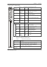
Laser Data
• Wavelength: 1300 nm
• Single-Mode Ports:
Transmit power (M15-155SF, M15-155MS SM ports, 9 µm SMF):
Minimum -15 dbm, Maximum -8 dbm
Receive power (M15-155SF, M15-155MS SM ports, 9 µm SMF):
Minimum -30 dbm, Maximum -8 dbm
• Multi-Mode Ports:
Transmit power (M15-155F, M15-155MS MM ports, 62.5 µm and 50 µm MMF):
Minimum -20 dbm, Maximum -14 dbm
Receive power (M15-155F, M15-155MS MM ports, 62.5 µm and 50 µm MMF):
Minimum -31 dbm, Maximum -14 dbm
Installing the Module
The M15-155 modules occupy one slot in the Avaya M770 chassis and can be
inserted into any available position. The Avaya M770 chassis ATM Backplane is
available in two versions: a single-domain or a dual domain ATM Backplane. If
you have the dual-domain version note that slots 1 to 7 and slots 8 to 14 in the
chassis function as two separate, unconnected ATM switching domains. Therefore,
if you intend to use several ATM modules as a single switch they should be on the
same side of the Avaya M770 chassis.
The M15-155 can be installed or removed while power is on.
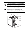
To install the M15-155:
• Hold the module (shaped like an upside down L) using both hands. The
colored module name panel and LEDs should be on top (see Figure 3).
• Fold out the plastic handles on the top and bottom of the front panel.