


M15-155 Installation Guide 5
Chapter 2
Installation
Installation Overview
There are several stages involved in the installation of the M15-155:
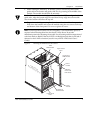
• Module Installation: Inserting the module in the Avaya M770 chassis and
connecting cables to the module’s ports for connection to other equipment such
as a switch or station.
• Command Line Interface (CLI): Connecting a terminal to the local console to
access the CLI and configuring all parameters. The CLI commands and the
explanation of how to configure the switch are described in the Avaya M770
ATM Switch User’s Guide.
Caution: The
M15-155 contains components sensitive to electrostatic discharge.
To prevent ESD damage, always hold the card by its sides only, and do not touch
the circuit board components unless instructed to do so.
Before handling the module or inserting it in the hub, touch the chassis of the hub
to discharge any electrostatic charge on your body.
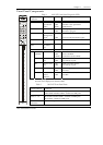
Note: The recommended Avaya M770 configuration is two M-PS800 units, plus a
third unit for redundancy. Such a configuration supports any number of ATM,
DomainX and Avaya M400 Gate Switch Modules in the chassis.
• One M-PS800 supports 7 M15-155 modules.
• One M-PS500 supports 4 M15-155 modules.
• Three M-PS500 support up to 12 M15-155 modules with no power supply
redundancy.
Laser Safety
The M15-155SF Single-Mode transceiver module and the two M15-155MS Single-
Mode transceiver ports are Class 1 Laser devices. They comply with IEC 825-1 and
Food and Drug Administration (FDA) 21 CFR 1040.10 and 1040.11.
The transceivers must be operated under recommended operating conditions.
CLASS 1
LASER PRODUCT