6-6
Carrier VFD Quick Reference
6.4 Troubleshooting the Drive Using Error Codes
The drive can display two kinds of error codes, called alarm and fault codes, to signal
a problem detected during self tuning or drive operation. Fault and alarm codes are
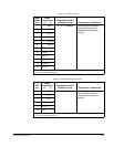
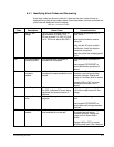
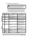
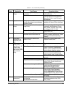
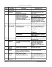
shown in tables 6.2 and 6.3. A special type of fault code, which occurs rarely, is the
fatal fault code. If the code you see is not in tables 6.2 or 6.3, refer to section 6.5 .
Alarm Codes
An alarm condition is signified by a two- or three-letter code flashing on the display.
The drive will continue to operate during the alarm condition. You should investigate
the cause of the alarm to ensure that it does not lead to a fault condition. The alarm
code remains on the display as long as the alarm condition exists. The drive
automatically clears the alarm code when the condition causing it is removed.
Fault Codes
A fault condition is also signified by a two- or three-letter code flashing on the display.
If a fault occurs, the drive coasts to stop and the RUNNING LED turns off. The first
fault detected is maintained flashing on the display, regardless of whether other faults
occur after it. The fault code remains on the display until it is cleared by the operator
using the STOP/RESET key or using the fault reset input from the selected control
source (P.000).
Error Log
The drive automatically stores all fault codes for faults that have occurred in the
system error log. The error log is accessible through the keypad, the optional OIM, or
the optional CS3000 software.There is no visual indication that there are faults in the
log. You must access the error log to view the faults.
The error log holds the 10 most recent faults that have occurred. The last fault to occur
is the first one to appear on the display when you access the error log. The faults in
the log are numbered sequentially. The most recent fault is identified with the highest
number (up to 9). Once the log is full, older faults are discarded from the log as new
faults occur.
For each entry in the error log, the system also displays the day and time that the fault
occurred. The day data is based on a relative 247-day counter (rolls over after
247.55). The time is based on a 24-hour clock. The first digits of the clock data
represent hours. The last two digits represent minutes. The clock can be reset using
P.030 (Elapsed Time Meter Reset).
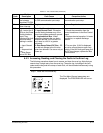
All entries in the error log and the day and time data are retained if power is lost. Refer
to section 6.4.3 for the procedure for accessing and clearing the error log using the
keypad.


