


14
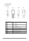
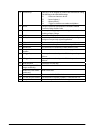
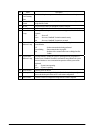
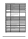
No. Name Description
5 Wall Mount
Unit Fastening
Plate
The holes in this plate accept screws that secure the wall mount unit in place.
6 Terminal Detect
Switch
This switch detects when the Handheld Terminal is not seated correctly on the
Bridge Satellite Cradle.
7 IR Port This port transfers data to the Handheld Terminal via IR port.
8 Power Contacts Power is supplied to the Handheld Terminal via these contacts.
This lamp indicates the power status and the mounting status of the Handheld
Terminal.
9 Power Indicator
Lamp
Off
Green
Red
: Power off
: Power on, Handheld Terminal mounted correctly
: Power on, Handheld Terminal not mounted
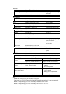
This lamp shows when the Handheld Terminal is performing data
communication.
10 Communication
Indicator Lamp
Off
Green flashing
Red
: No data communication being performed.
: Data communication in progress.
: Problem with a connection between two Bridge Satellite
Cradles.
This lamp indicates whether the system is operating normally. Regardless of
whether or not a Handheld Terminal is mounted this lamp indicates the system
status and whether or not a communication operation with the system can be
performed.
Off : System is not operating.
11 System Status
Indicator Lamp
Green : System is operating.
12 Power Switch Turns the power on and off.
13 Desktop Unit This is the base when using the Bridge Satellite Cradle in a desktop configuration.
Remove the desktop unit in the case of a wall-mount configuration.
14 DIP Switches Use these switches to configure the Bridge Satellite Cradle as required.