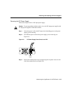
Removing and Installing Power Supplies
Book Title
4-18
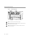
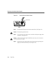
• Ground wire to ground connector
• Return wire to “+” connector
• Battery wire to “−” connector
Note Use 8 AWG copper conductor for the above connections.
Note Be sure to route the wires from the top of the terminal block, so that you do not
obstruct access to the unit’s power switch.
Step 6 After ensuring that all wire connections are secure, reinstall the terminal block
cover.
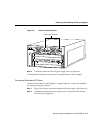
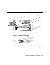
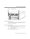
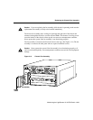
Step 7 The switch must be connected to the central office (CO) ground through the CO
ground connector shown in Figure 4-13.
Use the following guidelines when connecting the switch to CO ground:
• If this is a new installation, remove the adhesive strip covering the CO
ground connector on the switch.
• Use a copper ground wire lug and attach it to the switch using two 1/4-inch
M4 screws.
• Use an 8 AWG ground wire.
To complete the installation, see the section “Powering On the DC Power Supply” in this
chapter.


