


2
Cisco Security Device Manager (SDM) Quick Start Guide
78-16254-01
Use SDM to Configure the Router
Use SDM to Configure the Router
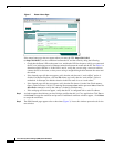
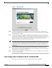
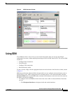
This section explains how to use the SDM Startup wizard to deploy your router with a working LAN and
WAN configuration. Once the router is deployed you can use SDM to further configure LAN and WAN
interfaces, dynamic routing, Network Address Translation (NAT), firewalls, Virtual Private Networks
(VPNs), and other features on your router. SDM runs under Internet Explorer version 5.5 or later, on a
PC that is running Microsoft Windows XP, Windows 2000, Windows ME, Windows NT 4.0 (with
Service Pack 4), or Windows 98. SDM runs under Netscape 4.79 on a PC that is running Microsoft
Windows XP, Windows 2000, Windows ME, or Windows NT 4.0 (with Service Pack 4).
Task 1: Install Interface Cards, and Cable the Router
Before SDM can be used to configure the router, you must install all the necessary hardware accessories
that are applicable to your router, such as WAN interface cards (WICs), Network Modules (NMs), or
AIM cards that you will use to connect to the network. Refer to the Quick Start Guide for your router
for instructions on installing these interface cards, cabling the router, and verifying that all the
connections are working properly.
Task 2: Set Up the PC
You have to set up the PC to communicate with SDM. SDM is shipped with a default configuration file
that assigns an IP address to a LAN interface on the router, and you must configure the PC to be on the
same subnet as the router’s LAN interface.
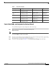
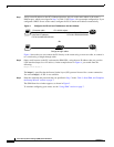
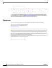
Because the router is not preconfigured as a DHCP server, you must assign a static IP address to the PC.
Assign an IP address in the range of 10.10.10.2 to 10.10.10. 6 to the Ethernet port of the PC, as shown
in Figure 1. Use the subnet mask 255.255.255.248. The lowest numbered Ethernet interface of the router
is preconfigured with the IP address 10.10.10.1.
Figure 1 Configure the PC with a Static IP Address in the 10.10.10.0 Subnet
Use an Ethernet cable to connect the PC’s Ethernet adapter to the lowest-numbered Ethernet port on the
router. See Table 1 to determine which port to connect the PC to, and what type of cable to use. The
Ethernet LED for your router listed in Table 1 turns on when the connection is made. Although Figure 1
does not show an Ethernet switch between the PC and the router, an Ethernet switch can be used with
straight through cables.
111011
Configure
static IP address
10.10.10.2/255.255.255.248
Factory configuration
10.10.10.1/255.255.255.248
10.10.10.0 subnet
Table 1 Router Port Numbers
Cisco Router Model Cable Type Port Number LED
831, 836, and 837 Straight through (standard) Ethernet ports 1, 2, 3, or 4 E1, E2, E3, or E4
1701 Crossover, or straight through
with Ethernet switch
Ethernet 10/100
(Yellow port on router)
ETH ACT